• Please review our updated Terms and Rules here

A/V DIN plug for vic20 same as TI99/4A

vic user

Veteran Member
Joined
Sep 12, 2003
Messages
724
Location
Ottawa, Canada
well, maybe not identical, i didn't really check, but over the weekend as i was moving some of my computer stuff around, i wanted to plug in the TI99/4A but the RF modulator i have for it is not very good.

i noticed that the DIN plug looked a heck of a lot like the one i use for my vic's, and so hoping that any power pins were in the same spots for both computers, i plugged the vic20 rf mod into the TI99/4A, and i got a nice clean crisp colour picture without blowing the computer or any fuses :)

i don't know if this is common knowledge about these DIN plugs, but maybe this will help someone looking for a replacement rf mod. for either computer.

chris
 
I even believe it was some pseudo-standard, and unless I'm totally wrong, the Atari 400/800 series also have a similar pin-out. Internet resources will tell the definite answer. However, I kind of remember reading that the TI-99 RF modulator uses 9V while the VIC one uses 5V. Maybe the electronics in that case would be fault-tolerant in either direction.
 
I would be careful because there used to be some issue about the hard to find TI/99 joysticks IIRC. I might however be confusing that with the RS CoCo joysticks. In any case different models of the Vic-20 used different power supplies. I have both models.

I notice I use "IIRC" increasingly more often. Nothing like actual documentation to combat memory fade. I won't even ask if the definitive Vic-20 site (can't remember his name) is still in existence. I'm finally beginning to learn that WWW sites have a shorter lifespan than hard drives.

With the present cost of gigabyte hard drives,
"Download my collector children, download." The whole effing site.

Lawrence
 
When it comes to Atari style joysticks, they should be interchangeable on Atari VCS and 8-bit computers, Commodore from VIC to Amiga, MSX and all other systems which support them, either natively or via an interface. I don't know if TI-99 uses digital or analogue joysticks and if it has a compatible interface, but if it does, it may be the first manufacturer after Atari's own VCS to be compatible. Paddles, light pens, mouse, drawing tablets etc may differ between the systems though.
 
Carlsen. Your signature is as incomprehensible as the Spam msgs. designed to get past anti-spam programs. Or else a google translation of bad nordic poetry. What's the key to this puzzle ?

Lawrence- (whose mother was Dansk and just as incomprehensible.)
 
Micom 2000 said:
Carlsen. Your signature is as incomprehensible as the Spam msgs. designed to get past anti-spam programs. Or else a google translation of bad nordic poetry. What's the key to this puzzle ?

Lawrence- (whose mother was Dansk and just as incomprehensible.)

Frank Zappa said:
"She's only thirteen, but she knows how to nasty!"

--T
 
Heh. It never fails to confuse people. I've used that bogus signature in a few places, and always the discussion goes out of topic; people asking me about the signature. The origin actually was some nonsense text from a spam message I got a couple of years ago. There was much more text than that, but those two "sentences" caught my attention. I fixed some words to get a slightly better flow, but that's it.

Speaking about DB9 joystick ports, I got the BBC Master Compact today (from Dimitri's sales). The earlier BBCs seem to have used a 15-pin analogue/digital connector, but this one has a 9-pin one which is said to be Atari compatible. I haven't had any chance to verify that yet.

My primary focus is to find a RGB pinout and figure out how to interface it to a 1084 or SCART. It has a 6-pin DIN, like e.g. Amstrad CPC and some other video equipment, but I'd not take for granted that all machines with this kind of video/RGB output have the same specs. So far I only found a terrible scan which appears to give this pinout:

Code:
   _ _
  / " \
 /5   1\
|   6   |
 \4   2/
  \_3_/

1 = Red
2 = Green
3 = Blue
4 = Composite sync
5 = ??? (it appears to be ground)
6 = +5V

That almost equals the CPC output, except for the CPC has luminance on pin 6. I found some links on how to make SCART out of the 5V TTL RGB, and it appears to be a bit of a project. The 1084 has something called analogue TTL, but maybe it is more along 0.7V (like SCART) than 5V.

http://www.sprow.co.uk/bbc/howto.htm#vgamonitor
http://www.howell1964.freeserve.co.uk/Acorn/BBCmicro/BBC_Enhancements.htm
 
Composite sync simply combines both signals on a single line, so it should work one way, but not the other (separating the two signals is a lot more difficult than combining them).

--T
 
In this case, I would feed a composite sync signal to an input expecting only horizontal sync, and leave the vertical sync unconnected. We'll see whenever I get to try it. The model with a DIN-8 (DIN 45326) explicitely states horiz/comp sync on the same pin, but it doesn't neccessarily mean the DB9 model has the same characteristics.
 
No, not sync-on-green. The computer outputs R, G, B and a composite sync, the monitor expects R, G, B, intensity, horizontal and maybe vertical sync. It appears one should wire 0V (ground) to intensity which may give a bit dark picture - I suppose 5V would give it a bright picture on the other hand.
 
Good news: the 1084SDD (or whatever the stereo version with a DSUB should be called) in TTL mode indeed syncs with a composite sync signal on horizontal sync.

Bad news: I only got red text, and it faded away into nothing. I have to check my cable, maybe intensity should be wired to +5V instead of 0V..

Good news: Nothing seems to be broken (so far)

Bad news: Of course I don't have a suitable monitor so I can test that the RGB output from the computer is good.

Good news: If I turn off the monitor, wait a while and turn it on again, the red text shows, but slowly fades away.

Bad news: A couple of years ago this monitor broke down, it was repaired and since then the CVBS input doesn't sync properly on bright colours. I suspect one component was replaced with another of a different value, and has got suggestions from people over Internet what to look for. While I've never used the TTL mode before, it is likely that it got damaged when the monitor was repaired.

Good news: I found a BBC mailing list where similar questions have been asked and answered before many times, so I'll post there.
 
Last edited:
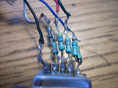
In the end, I followed advice and converted the digital TTL RGB signals to analog 1V RGB signals using some resistors. The specs said 330 ohm or higher. I tried 2.2k ohm, but it dropped the voltage too far so the monitor won't sync. Around 470 ohm worked however.

bbc-kabel.jpg

I'm not very good with a soldering iron, in particular not an old, dull one that cools down at random intervals. The good point is that I will never make my own electronically triggered bombs or alike; it would take me too long and in the end they may not work.
 
carlsson said:
BBC Master Compact [..] has a 9-pin one which is said to be Atari compatible.
I finally found one application note (in PostScript format) that uses the following pinout:

Code:
_____________
\ 1 2 3 4 5 /
 \_6_7_8_9_/

1 = PB3, 2 = PB2, 3 = PB1, 4 = PB4, 5 = CB1, 6 = PB0, 7 = +5V, 8 = 0V, 9 = CB2/LPTSTB

Apart from I don't know if the directions are correct, it seems to match the common Atari/Commodore/whatever interface:

1 = JOY0, 2 = JOY1, 3 = JOY2, 4 = JOY3, 5 = POTY, 6 = FIRE/LIGHTPEN, 7 = +5V, 8 = GND, 9 = POTX

However, this type of interface was only available on this model, so it is likely that any software I download will not support it?
 
Back
Top