Hi All,
I'm repairing a bunch of cut traces on the front panel PCB of my Altair 8800. I could use the schematics but it would be much easier for me if someone could just post or send me a high resolution photo of the back (wire connecting, not lights/switches) side of the panel. Could anyone spare a moment to take a clear pic of theirs for me or point me to a good one that already exists? I've searched and searched already but haven't found it.
Thanks!
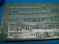
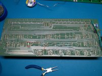
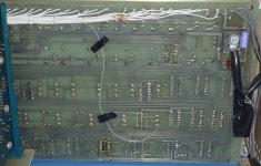
Here are the photos of mine right now. You can see some cuts are very obvious and will be easy to fix but there's a little more activity, cutting and patching already done around 2 of the ICs that are harder for me to figure out. One good photo will go a long way in helping me get this back together.


Last edited:

