• Please review our updated Terms and Rules here

Anybody have info on GL1016 regulator?

GearTechWolf

Experienced Member
Joined
Apr 24, 2015
Messages
264
Location
Washington
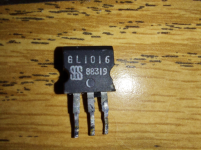
Came from a C64 epoxy-brick PS but didn't survive disassembly, need data so I can replace with a comparable/equivalent part.
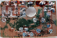
Alternately, going by the rest of the circuit, would the pin-out I've marked be correct?
The broken part-GL1016.png
The board with crude annotations- C64PS-17.png
Once I get an applicable regulator subbed in, I can do a smoke-test with mostly original components! (not attaching it to any computer until I build the saver circuit)
If it passes that, I'll load-test with a dummy load and see how it fares.
Thanks for any help!
 
The first link is mostly useful for the picture of the far more intact circuit-board as that will be far easier to convert into an image that can be used to duplicate the board.
But the second is very useful as it points out the flaw in that schematic and provides an improved one, very helpful for the new one I'm building!
Thanks for the help!

Still wish I could confirm that a 7805 would be a drop-in replacement for the GL1016, but I may just risk installing one and seeing what happens, since I have more than one of them.
 
Installed, tested, and it works perfectly with all-original components! (aside from the regulator, of course) A nice, stable, +5 volts and 9VAC.
 
Addendum- The LM7805 is a pin-perfect drop-in replacement for the original GL1016 regulator. (just to be clear for future readers)
 
GearTechWolf,
I've repaired many of those Power supplies by adding an External Heat sink and used
a Motorola MCT7805 +5 Volt Regulator at 1.5 AMPS output. Most of the 7805 series
are 1 AMP output devices. As far as I know none of the supplies I repaired ever quit.
I just ground off the original PCB traces to the +5 Volt regulator and added heavy wires
to my external Motorola MCT7805 Regulator. I used Black RTV (Silicone Caulk) to
reattach the Bottom of the Brick. A quick and easy fix.

Somewhere I have a drawing of the PCB traces, and what each PCB trace is.

Larry
 
That's a good quick fix! 2.2 amps should be enough for most uses and the MCT7805 has far better built-in protection circuitry than the originals.
For at least one of the two supplies I'm rebuilding I'm planning to use a big ol' SK 3052P with a better heat-sink.
Also, I should have specified, but the 7805 I used in the otherwise-all-original-parts test is in fact an MCT7805, but thanks for making sure!
I'm undecided as-yet on whether I'll bother extracting the components of the second power-supply from their epoxy prison, aside from the regulator.
That drawing of the traces could be useful, if I ever choose to get some replica PCBs made.
(as the originals are a bit beat-up, although the second is fully intact, just a little dirty and bent)
 
Back
Top