• Please review our updated Terms and Rules here

Apple Monitor IIc A2M4090 Hitachi variant - Setting proper B+ voltage

VERAULT

Veteran Member
Joined
Jan 30, 2012
Messages
8,434
Location
Connecticut, USA
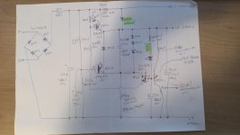
I found in my crypt of stuff an Apple Monitor IIc I thought I had repaired, but marked as bad. Went over the board and replaced some leaky caps. I noticed I replaced the diodes in the bridge rectifier. And I also replaced the potentiometer for setting B+. I vaguely remember it was cracked. After some tweaking I was able to get the sound of highvoltage but no CRT display. I tweaked the new B+ pot and The filament started to glow and the picture came on. I have to all but max the pot out to get the best picture. I may be using the wrong potentiometer. Keep in mind this is the hitachi variant, not the Samsung model which is the only version covered in SAMS computer facts (so Sams is useless for troubleshooting this model CRT)

I watched ADB video here:
But I still dont know what the B+ voltage should be set to or how to properly check it (can it be checked without the CRT board connected as in the video?

Would appreciate some input.


Edit: BTW, I noticed a sligh back off on the B+ pot stops or greatly reduces the waviness that can be so bad on these models. Might just be coincidence.
 
Last edited:
Probably most of these small VDU's use a 12V B+, but not all some use 18V. They generally went to a system where the B+ is injected into the LOPT (line opt transformer)via a diode and they have a capacitor on an additional winding that charges to around the B+ plus 6V, so 18V DC appears on one of the LOPTY terminals that has an electrolytic cap connected to it. It was like this in the Apple IIc (sams version) I think. Earlier LOPT's didn't use this system and the extra winding, diode and electrolytic cap were not there.

If all is well, then all the other important voltages generated by the flyback transformer will be correct. Also if the B+ is off in value, it alters the raster size. So assuming that is about correct, and the width coil has not been touched, the voltages should be close to correct.

If the supply voltage to the H output stage is manipulated, generally the raster size (and EHT) will increase with increasing supply voltage, but there are two opposing effects which moderate this, it is not a linear relationship. The current in the H yoke coils rises at a rate of V/L (after the HOT switches on) where V is the supply voltage and L is the yoke's inductance. However the amount of deflection you get is inversely proportional to the square root of the EHT voltage, and the EHT voltage is proportional the the supply voltage too. So for argument's sake (not that anyone would do it) if you double the supply voltage to the H output stage, the width would increase by a factor of 2/root2 or 1.41, not double as one might intuitively expect.

For example if the supply voltage was 12V normally, and you increased it by 20% say to 14.4V , the scan width would increase by a factor of 1.2/root(1.2) = 1.095 or about 10%. However, the EHT will have increased by 20% and that can be risky for the EHT rectifier. Still, the raster size is a good guide (assuming nobody has tweaked the width inductor or the height pot) as to whether the correct voltages are present at the H output stage.

(I have just posted a thread about trying to find the Apple Mac VDU schematic, that I am looking for)

(Currently I'm doing a study of the LOPT's (flyback transformers) used in early computer VDU's. Can you have a look and see if there is a type number stamped on the flyback transformer in your Hitachi VDU ? )
 
Last edited:
I couldnt tell you what is was as the pot was replaced (it has cracked in half) I have a 1M Ohm 105 pot on there now. I did notice increasing B+ increases the size of the picture as well as the intensity. 2433911 DL27T and HITACHI ULD2 are all that are stamped on the flyback. Its tough to see since its surrounded by a Can.

And I am getting 10.37 VDC from B+ right now. If I get it up to 10.4 the waviness its noticeable.
Thanks.

Probably there is something wrong with the regulator circuit, perhaps there is some ripple in it too, as likely it is supposed to be a 12V supply, or in the range 11.5V to 12V. One way to tell is to check where the CRT heater is connected, as typically these CRT's of the era for computer VDU's and industrial displays used 12V heaters. The CRT might be one where the data on its gun/heater is available. Often they put a Low R value resistor in series with the heater too, which limits the turn on current surge when the heater is cold, but it normally, when the heater is warm, it drops less than one volt.

It might be necessary to trace out the regulator section schematic, to examine it and formulate a plan to test it.

1M Ohm sounds like a very high value pot to be in a low voltage regulator circuit where the pot would set some sort of reference voltage, the original value might have been a much lower value. If the voltage across the pot is less than 30V you could try a much lower value like 10k to 47k. If there are resistors in series with the pot terminals, the value of those might give some idea of the expected currents in that area. A pot of 1M might be expected say in the CRT's grid bias or focus circuits.
 
1M sounds high to me as well. I wish I remember the circumstances of when I put it on. It may have been the only ones I had. I do have some 20K ones on order for a 1541 commodore drive I am working on. They should be here in the next day or so. I can try one of those.
 
I have been running the CRT outside of its enclosure as is for over 4 hours (running the prince of persia demo at 4X speed on my IIc Plus), just to burn in the new caps and check stability. So far no change in picture quality but the B+ has dropped to 9.95 VDC. I wish I knew the proper operating voltages on these hitachi monitors. I have worked on maybe 15 to 20 by now and they are much more common than the Samsung (I do like the samsung variant better, it seems more robust and rarely needs much work). I will run it for another couple hours until I turn it off for the night.
 
Sorry the model number confused me, as its the one referenced in the schematic. Hrm I'll dig a little more... My brain is just not booting right today. :\
 
Its the same exact model number but all the guts are different. Apple did that with monitors and keyboards, and who knows what else. Looks the same on the outside but different manufacturer and layout inside.
And like I said.. The hitachi models are the most common. I have worked on a couple dozen and maybe only 3 samsungs. I am guessing Sams manuals just grabbed/bought one and assumed they were all the same and as luck would have it they got the less common one covered.

Really this comes down to being Apples fault for not releasing very much of thier equipments technical info and schematics. I have a large pile of color composite monitors I cant repair because Schematics DONT exist anywhere.
 
The new Pots should be arriving in todays mail. But while waiting for them I had a thought. Just as in this video at this timestamp:
I had to rebuild the bridge rectifier as they crumbled to dust. If I put on to restrictive a diode could that cause the low B+? I can tell you the heat coming off the bridge rectifier is pretty serious.
 
Really this comes down to being Apples fault for not releasing very much of thier equipments technical info and schematics. I have a large pile of color composite monitors I cant repair because Schematics DONT exist anywhere.

I have been confronted with this exact same problem many times.

For example one VDU I have was made by Conrac for a Military Radar contract. No service manual or schematic exists for it, at least that was available to the public. I realized to get "control" over it, I would have to sit down at my desk, examine the pcb's, identify the components as best possible, initially hand draw the schematic with pencil & paper, then create a neat copy.

It is amazing what you can deduce from what is in front of you. For example I was able to determine the expected main power transformer output voltages, because I knew that one of its windings produced a certain voltage for the CRT's heater. I could apply a small diagnostic voltage and calculate all the winding voltages that way. Also, by looking up the data sheets on the active devices, I could gain more data.

After a while I had re-created the entire schematic and was able to successfully power and run the VDU. (More awkward than usual too, because it ran from a 3 phase power source typically found in an aircraft).

You can see all of the schematics I created for it, in this article:


But the thing I am getting at is; don't be daunted by the lack of the schematic. If you are prepared to spend the time you can create the whole thing yourself. I also did a similar thing creating what amounts to a service manual for the PSU in the IBM 5155. As soon as I saw there was no manual for it, I thought, hello, here we go again:


Many years ago a fellow I worked for was talking about the need for service manuals on the equipment we were servicing, he said: "Never get into bed with a piece of equipment without its manual".

So paying heed to that remark I have a manual for everything in my workshop and if I don't have one and can't get one for some specific equipment, I make one myself. Then even a decade or two later, it has a habit of coming in handy when that thing breaks down.
 
Last edited:
Hello all! Sorry to respawn this old thread but I'm needing some help. I've bought an Apple IIc 9" Monochrome monitor just like this topic models. It was in a very bad shape since it was found in a dumping terrain in São Paulo, Brazil. The seller told me it was not working and took the caution to make a very good shipping box. It came exactly as found. Well, I took it apart using the Adrian's Basement video. Took every single piece apart, make a retr0bright of the case. It's the Hitachi variant and the first thing I noticed was the 4 rectifing diodes on the rectifying bridge totally missing hehe... another diode that seems the same part on the power supply board was broken as well. Changed to 4 x 1N4007 and another 1N4007 on the board. Then the power supply turned on and is giving like +20V on the +B voltage pin. Adjusting the +B trimpot didn't changed.. 19.8 to 20.2V only. When I've pluged the power supply to the analog board, 2 of the 4 rectifying bridges diodes smoked. I've try to find the Hitachi variant schematics with no success. Does anybody have this schematic? Thanks in advance! Attached the power supply board schematic draft I've made by hand...
 

Attachments

  • 1.jpg
    1.jpg
    122.1 KB · Views: 3
Its not an "Old Thread". If it was from 2007 sure...


If its those white ceramic "ball" style diodes they disintegrate to powder if exposed to prolonged moisture.

Sounds like maybe you had the orientation of the diodes wrong when rebuilding the bridge rectifier. If I had to make a guess.
 
Thanks for replying!
The power supply worked ok without the load (ie, unplugged from the monitor PCB), but I didn't tested with a proper load (an incandescent lamp for example).
I'll double check the diode's polarity and will test the power supply again using some load.
Besides, I'll check for some short circuit on the monitor PCB parts.
 
Back
Top