NeXT
Veteran Member
****CLICK HERE FOR PART 1****
At this point the itch which was the totally basic CCU in this machine was getting to me. The basic model CCU is called the UCC6. It contains nothing but the power supply, selector driver, the power supply for the paper tape reader and a selector switch for either local use of the machine for connection to a host.
I again looked at the fancy buttons and rotary dial that the TWC controller was fitted with. Totally useless….or were they? I knew already that the model 33 could be outfitted with a modem but at this point you had better luck finding a Dataphone than you did the proper CCU to go with it (ironically while I was working on this project a suitable Dataphone DID pop up on ebay….and sold for an absurd $550!) so I had to think about what else I could do. Well not long after the model 33 left production one of the biggest advancements and standardizations in modems came about. Hayes Microcomputer Produtcs released the Smartmodem.
This self-contained piece of genius did everything the Bell 103 (and as a result, the 101) could, PLUS a hell of a lot more using a combination of dip switches and programmable registers. Included with all those fancy features was the ability to leave your computer and modem on and have the modem answer a data call on its own. By now the Bell 103 standard is the absolute basic standard that ALL modems support. Regardless of make or model, hardware or DSP/Winmodem, everything can talk at the Bell 103 standard. The catch here however is that a Teletype can only do Bell 101 because of its 10 CPS limitation so we can now connect to any other modem on the planet and they can call the teletype if they so desire, but unless you’ve forced the host machine’s UART to only operate at 110 baud (that rules out the use of Winmodems and DSP modems which were programmed to select speeds and have no idea what to do when you try to force a speed it doesn’t know of) it will stick strictly to modulation at the Bell 103 standard which the teletype will freak out about.
Anyways, we plug a Smartmodem into a teletype and boom, we’re done.
>>VIDEO<<
No, we are not. You might of done it but you’ve cheated. We still have a boring looking teletype machine with a modem and an RS-232 adapter hanging out the back. Dialing is purely a function we have to do over the keyboard and if you have no idea how to use the Hayes AT command set you’re pooched. If we are going to slap a modem onto a teletype like this we’re going to make it look as clean as possible and if we have all these amazing functions in the modem, we’re going to use them…somehow.
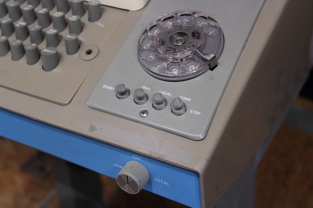
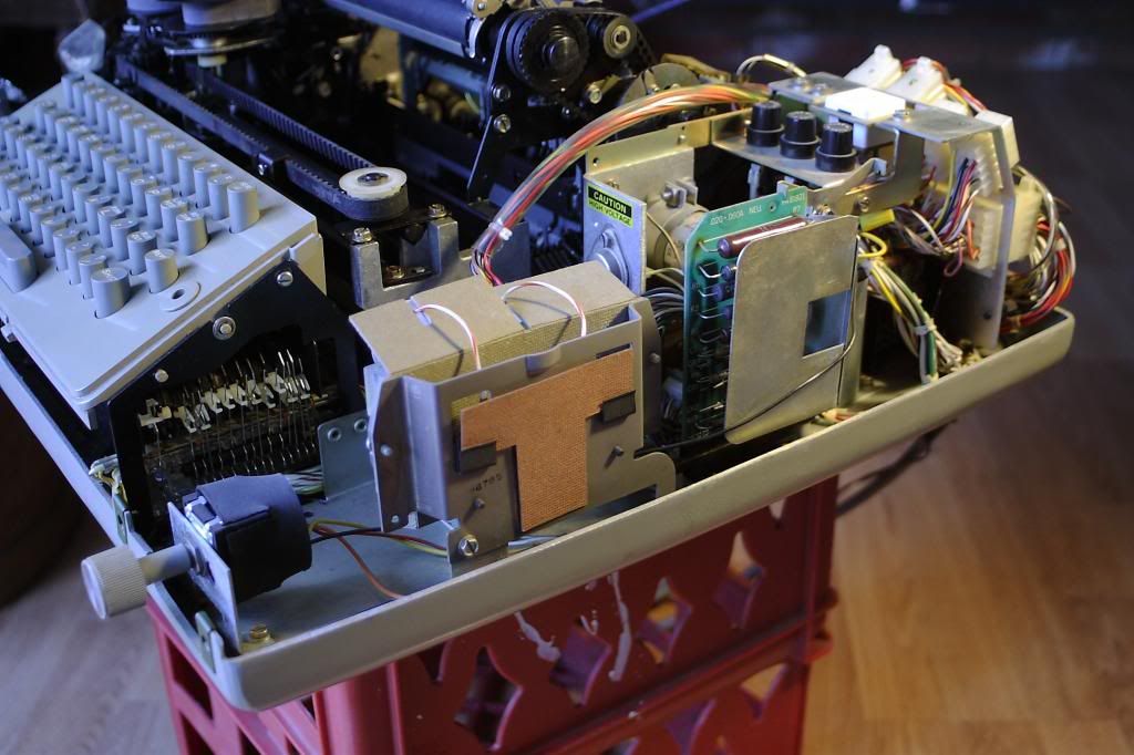
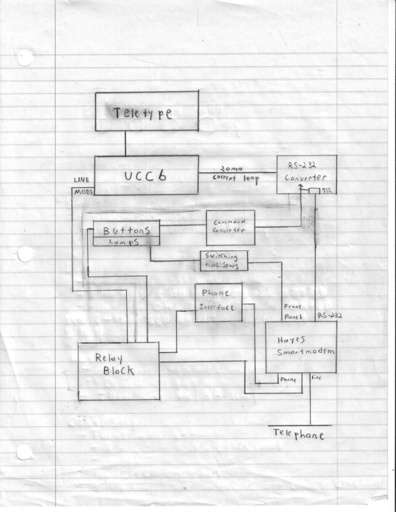
I spent a good two days just looking over all the documentation I had and anything I could find and just playing with the parts on hand to see how things fit. In the end thanks to how modular Teletype had made the CCU’s and the fact that I had by off chance a spare paper tape power supply designed for mounting in the metal stand I did not yet own, short of the modem we could cram a hell of a lot into the cavity for the CCU. We could add buttons. We could add feedback lights…we could possibly even use the rotary dial.
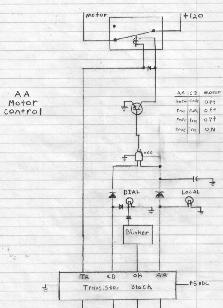
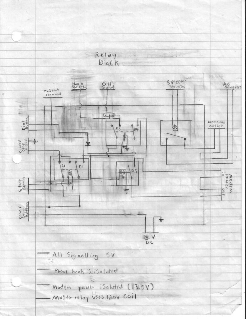
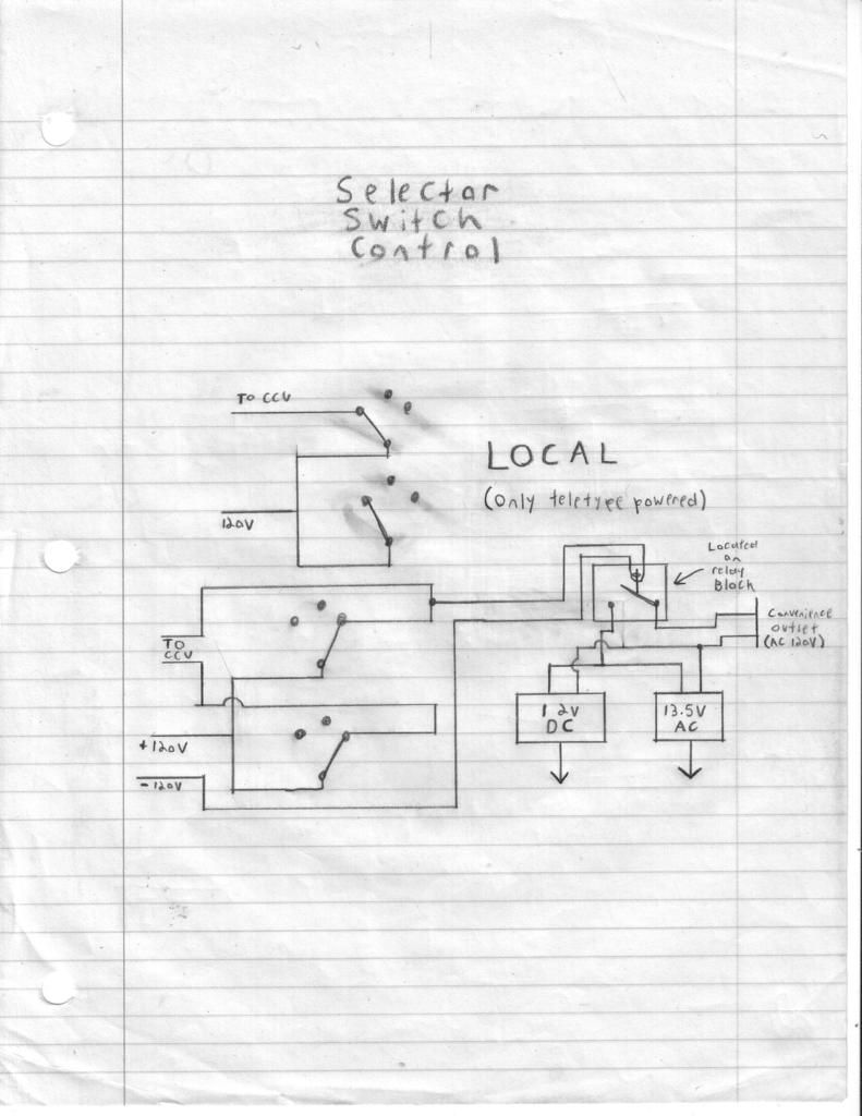
>>THE REST OF THE DIAGRAMS, FOR YOUR VIEWING PLEASURE<<
***UPDATE: As of March 2017 due to Dropbox culling the Public folder the link above will no longer be useable. As of this update (December 2016) I do not have an alternate location to host the file long term.***
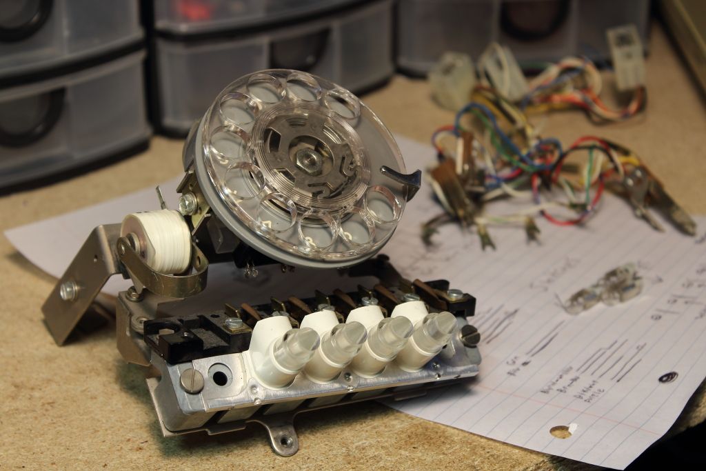
One of the first things I had to do was move the assembly that held the buttons, lamps and the dial from the TWX controller to the UCC6. Along the way I found that some things didn’t exactly line up but then again I was trying to do things that Teletype never offered. A screw tab had to be cut off and a new bracket had to be fabricated to mount the selector switch. The old wiring harness was removed and a new perfboard was created with a set of microswitches to give the buttons a more natural feel when pressed. Underneath the dialing bracket I drilled two holes and threaded in standoffs. When you strip the voice circuits out of a telephone you can make it quite compact when pulse dialing is used. This board would become the entire telephone circuit inside the unit with the sole task of holding a hook switch, pulse dialing the line when off hook and ringing the bell when someone was calling.
>>IMAGE<<
>>IMAGE<<
****CLICK HERE FOR PART 3****
At this point the itch which was the totally basic CCU in this machine was getting to me. The basic model CCU is called the UCC6. It contains nothing but the power supply, selector driver, the power supply for the paper tape reader and a selector switch for either local use of the machine for connection to a host.
I again looked at the fancy buttons and rotary dial that the TWC controller was fitted with. Totally useless….or were they? I knew already that the model 33 could be outfitted with a modem but at this point you had better luck finding a Dataphone than you did the proper CCU to go with it (ironically while I was working on this project a suitable Dataphone DID pop up on ebay….and sold for an absurd $550!) so I had to think about what else I could do. Well not long after the model 33 left production one of the biggest advancements and standardizations in modems came about. Hayes Microcomputer Produtcs released the Smartmodem.
This self-contained piece of genius did everything the Bell 103 (and as a result, the 101) could, PLUS a hell of a lot more using a combination of dip switches and programmable registers. Included with all those fancy features was the ability to leave your computer and modem on and have the modem answer a data call on its own. By now the Bell 103 standard is the absolute basic standard that ALL modems support. Regardless of make or model, hardware or DSP/Winmodem, everything can talk at the Bell 103 standard. The catch here however is that a Teletype can only do Bell 101 because of its 10 CPS limitation so we can now connect to any other modem on the planet and they can call the teletype if they so desire, but unless you’ve forced the host machine’s UART to only operate at 110 baud (that rules out the use of Winmodems and DSP modems which were programmed to select speeds and have no idea what to do when you try to force a speed it doesn’t know of) it will stick strictly to modulation at the Bell 103 standard which the teletype will freak out about.
Anyways, we plug a Smartmodem into a teletype and boom, we’re done.
>>VIDEO<<
No, we are not. You might of done it but you’ve cheated. We still have a boring looking teletype machine with a modem and an RS-232 adapter hanging out the back. Dialing is purely a function we have to do over the keyboard and if you have no idea how to use the Hayes AT command set you’re pooched. If we are going to slap a modem onto a teletype like this we’re going to make it look as clean as possible and if we have all these amazing functions in the modem, we’re going to use them…somehow.
I spent a good two days just looking over all the documentation I had and anything I could find and just playing with the parts on hand to see how things fit. In the end thanks to how modular Teletype had made the CCU’s and the fact that I had by off chance a spare paper tape power supply designed for mounting in the metal stand I did not yet own, short of the modem we could cram a hell of a lot into the cavity for the CCU. We could add buttons. We could add feedback lights…we could possibly even use the rotary dial.
>>THE REST OF THE DIAGRAMS, FOR YOUR VIEWING PLEASURE<<
***UPDATE: As of March 2017 due to Dropbox culling the Public folder the link above will no longer be useable. As of this update (December 2016) I do not have an alternate location to host the file long term.***
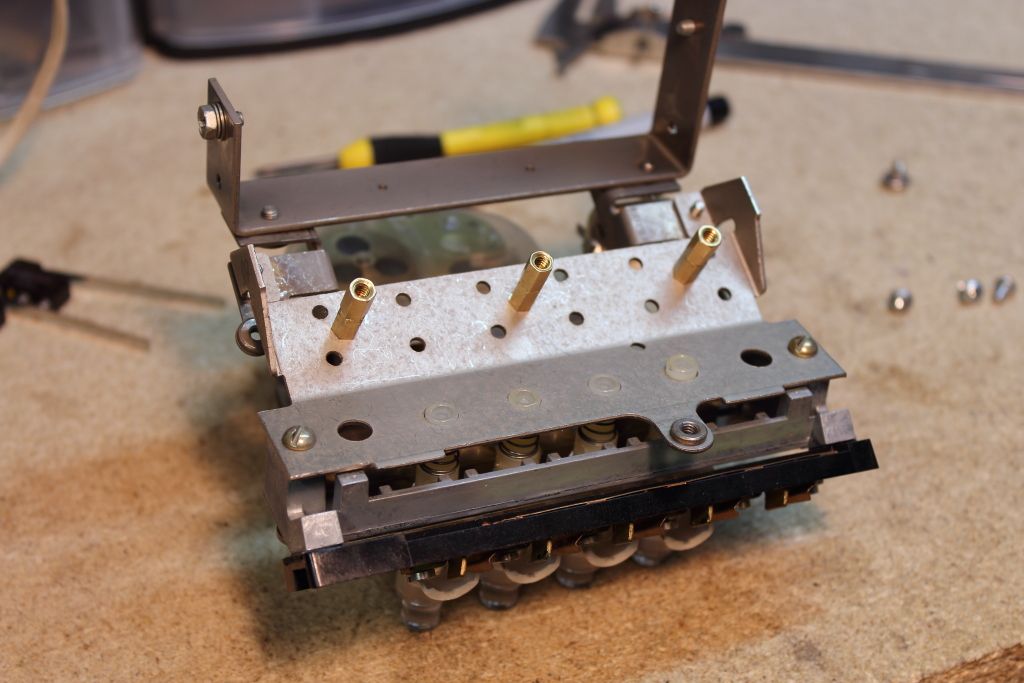
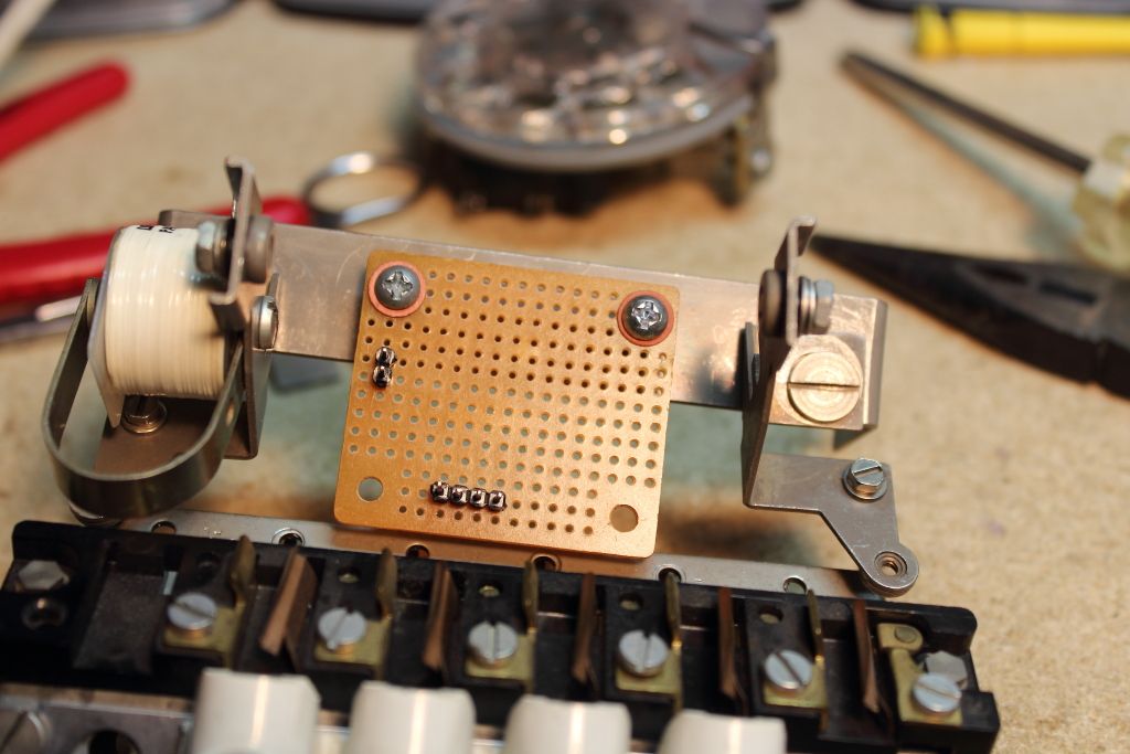
One of the first things I had to do was move the assembly that held the buttons, lamps and the dial from the TWX controller to the UCC6. Along the way I found that some things didn’t exactly line up but then again I was trying to do things that Teletype never offered. A screw tab had to be cut off and a new bracket had to be fabricated to mount the selector switch. The old wiring harness was removed and a new perfboard was created with a set of microswitches to give the buttons a more natural feel when pressed. Underneath the dialing bracket I drilled two holes and threaded in standoffs. When you strip the voice circuits out of a telephone you can make it quite compact when pulse dialing is used. This board would become the entire telephone circuit inside the unit with the sole task of holding a hook switch, pulse dialing the line when off hook and ringing the bell when someone was calling.
>>IMAGE<<
>>IMAGE<<
****CLICK HERE FOR PART 3****