NeXT
Veteran Member
****CLICK HERE FOR PART 3****
I was now approaching a point where I could do a test of using the rotary dial to place the call while the modem listened. The command ATD was sent to the modem, the hook switch was manually activated and I tried to dial. Nothing. Something wasn’t working. After a few days trying to understand what was wrong I decided to put that aside for now and move onwards.
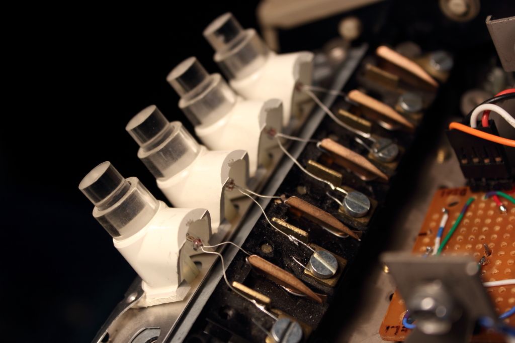
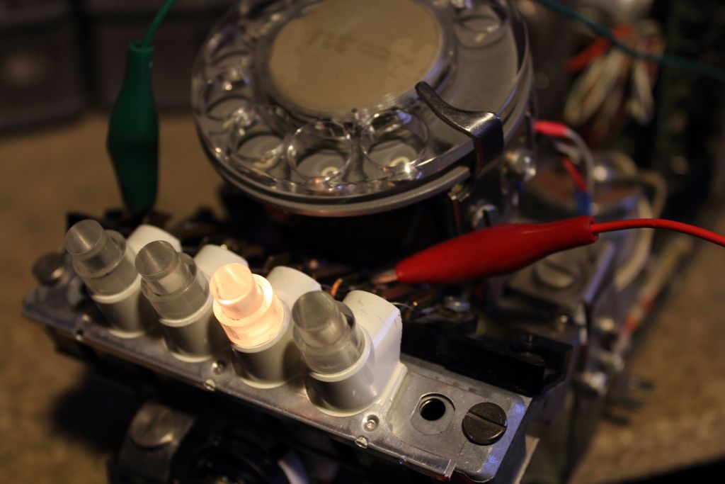
The original lamps in the buttons unfortunately had to be replaced. All the substitutes I found were generally quite expensive. My preference was to not use LED’s for these buttons at all cost because white LED’s did not yet exist and naturally they were illuminated by the glow of incandescent bulbs. Eventually I came across 6.3v Grain of Rice bulbs which gave off the perfect amount of light at 5v which would also help prolong their life.
Powering everything felt like it was going to be a job for a new supply. Because I was using two of the buttons to turn the electronics on or off I needed to add two relays. One brings up the main +5 and +12v supplies while the other was to turn the modem on or off which had to use its own power supply as it wanted 13v AC. I decided to accomplish this by first having one relay be tied to the circuit which operates the teletype’s receive circuit in LINE mode. Once it closed 120v would flow to an outlet hidden away under the machine. The +5 and +12 could then come up on their own and once you decided to turn the circuit on 5v would flow to the modem’s power relay and switch it on as well.
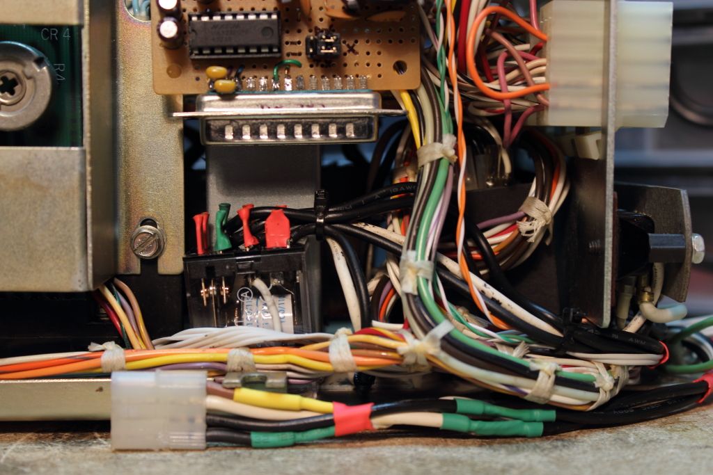
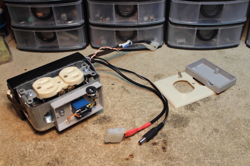
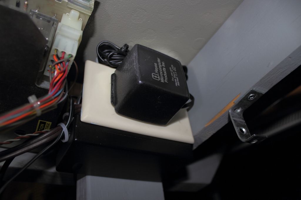
I decided against hardwiring in the original Hayes adapter in favor of buying a proper plug for it. In fact, for everything I decided it would be best to make things pluggable between what was mounted inside the teletype and outside. It would make for separation of the machine from the stand a lot easier.
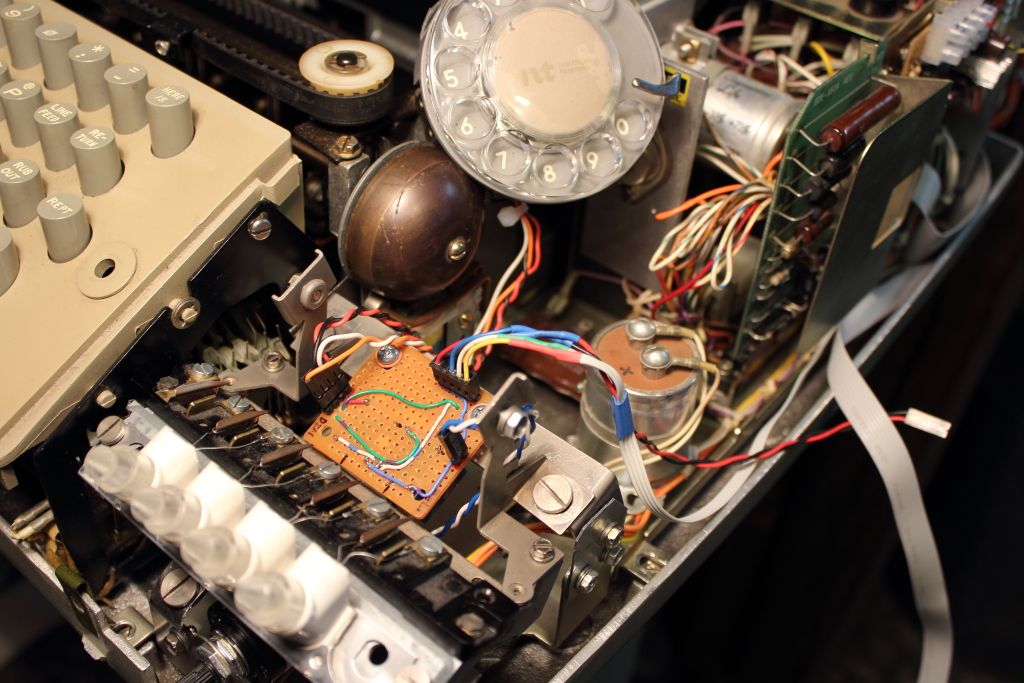
The next issue I had to deal with was how to actually interface with the modem. Technically I did have the RS-232 connection but I could not easily get the status on the various indicator registers. The LED’s also operated with reverse logic. In the end I realized that I can feed the LED’s through a 74LS04 to reverse it and then I could use the LED’s to give me the information out of the modem that I needed like if it was off hook or if the receiving modem had picked up or if Auto Answer was on. Routing it from the modem to the teletype was as simple as a ribbon cable with yet another disconnect point.
While I really wanted to make everything relay and transistor driven one thing I could not figure out was how to do so without a microcontroller. The main issue was the lack of space I had. I would somehow have to form the strings of ASCII data and transmit it on cue at a set baud rate. Nothing I investigated seemed promising. Eventually I decided to once again turn to one of my favourite microcontrollers, the Pro Mini.
When the DIAL button was pressed, 5V was sent to a digital input pin. This in turn makes the controller spit out the control string to take the modem off hook and listen for a carrier. Then LOCAL was pressed it would toggle the modem’s S0 register to 1 which enabled automatic answer and on a second press would reset it back to 0. Getting it to the modem however was another issue.
On my serial paper tape reader project I had simply tied the TxD line from the reader to the TxD output on the terminal I used it with. While it worked there it was a real hack given how RS-232 relies on +5/-5v signaling and I was technically making it work only at +5/0v and my current loop adapter was not at all happy about it. We could not inject into the existing RS-232 line.
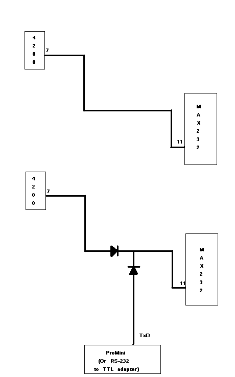
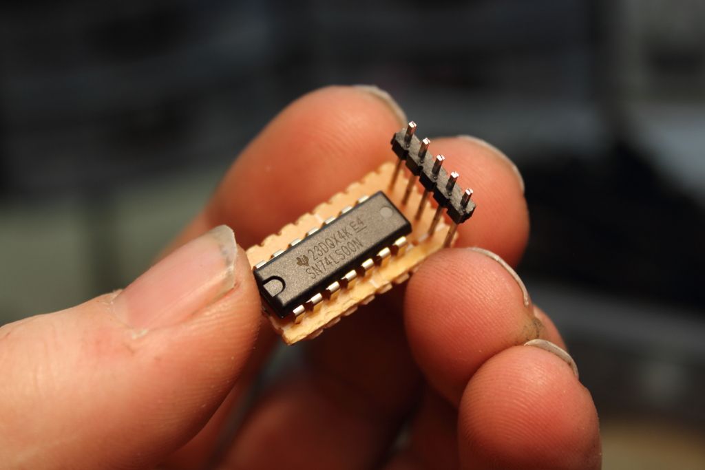
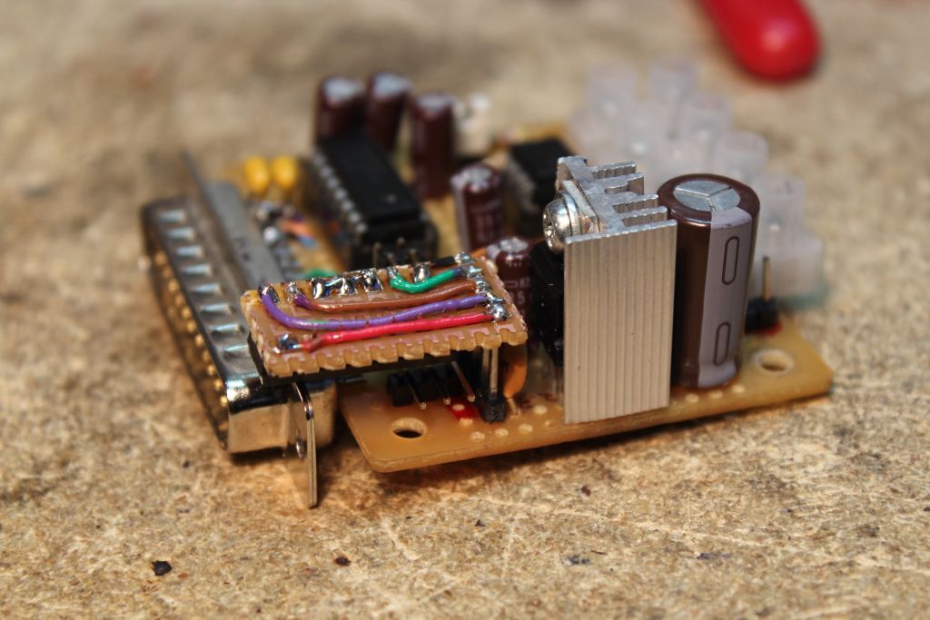
We would have to take the TTL serial data from the microcontroller and put it through a MAX232 to make it work. We already had one of these chips present on the current loop adapter but after again trying to make it work with diodes I frustratingly gave up and looked into using an IC. I could make it work by feeding both inputs to the MAX through a 74LS00N first but physically I was out of space on the adapter. Instead I opted for a riser and small PCB which would let me mount the one chip over the input pins from the microcontroller and the serial port. It looked kludgy but again, it worked.
>>IMAGE<<
****CLICK HERE FOR PART 5****
I was now approaching a point where I could do a test of using the rotary dial to place the call while the modem listened. The command ATD was sent to the modem, the hook switch was manually activated and I tried to dial. Nothing. Something wasn’t working. After a few days trying to understand what was wrong I decided to put that aside for now and move onwards.
The original lamps in the buttons unfortunately had to be replaced. All the substitutes I found were generally quite expensive. My preference was to not use LED’s for these buttons at all cost because white LED’s did not yet exist and naturally they were illuminated by the glow of incandescent bulbs. Eventually I came across 6.3v Grain of Rice bulbs which gave off the perfect amount of light at 5v which would also help prolong their life.
Powering everything felt like it was going to be a job for a new supply. Because I was using two of the buttons to turn the electronics on or off I needed to add two relays. One brings up the main +5 and +12v supplies while the other was to turn the modem on or off which had to use its own power supply as it wanted 13v AC. I decided to accomplish this by first having one relay be tied to the circuit which operates the teletype’s receive circuit in LINE mode. Once it closed 120v would flow to an outlet hidden away under the machine. The +5 and +12 could then come up on their own and once you decided to turn the circuit on 5v would flow to the modem’s power relay and switch it on as well.
I decided against hardwiring in the original Hayes adapter in favor of buying a proper plug for it. In fact, for everything I decided it would be best to make things pluggable between what was mounted inside the teletype and outside. It would make for separation of the machine from the stand a lot easier.
The next issue I had to deal with was how to actually interface with the modem. Technically I did have the RS-232 connection but I could not easily get the status on the various indicator registers. The LED’s also operated with reverse logic. In the end I realized that I can feed the LED’s through a 74LS04 to reverse it and then I could use the LED’s to give me the information out of the modem that I needed like if it was off hook or if the receiving modem had picked up or if Auto Answer was on. Routing it from the modem to the teletype was as simple as a ribbon cable with yet another disconnect point.
While I really wanted to make everything relay and transistor driven one thing I could not figure out was how to do so without a microcontroller. The main issue was the lack of space I had. I would somehow have to form the strings of ASCII data and transmit it on cue at a set baud rate. Nothing I investigated seemed promising. Eventually I decided to once again turn to one of my favourite microcontrollers, the Pro Mini.
When the DIAL button was pressed, 5V was sent to a digital input pin. This in turn makes the controller spit out the control string to take the modem off hook and listen for a carrier. Then LOCAL was pressed it would toggle the modem’s S0 register to 1 which enabled automatic answer and on a second press would reset it back to 0. Getting it to the modem however was another issue.
On my serial paper tape reader project I had simply tied the TxD line from the reader to the TxD output on the terminal I used it with. While it worked there it was a real hack given how RS-232 relies on +5/-5v signaling and I was technically making it work only at +5/0v and my current loop adapter was not at all happy about it. We could not inject into the existing RS-232 line.
We would have to take the TTL serial data from the microcontroller and put it through a MAX232 to make it work. We already had one of these chips present on the current loop adapter but after again trying to make it work with diodes I frustratingly gave up and looked into using an IC. I could make it work by feeding both inputs to the MAX through a 74LS00N first but physically I was out of space on the adapter. Instead I opted for a riser and small PCB which would let me mount the one chip over the input pins from the microcontroller and the serial port. It looked kludgy but again, it worked.
>>IMAGE<<
****CLICK HERE FOR PART 5****