NeXT
Veteran Member
****CLICK HERE FOR PART 4****
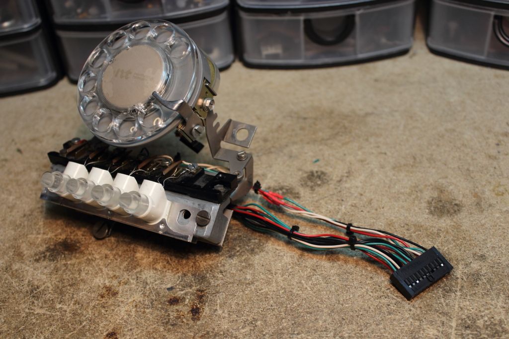
Continuing with me wanting to make everything pluggable in some fashion for the sake of making work on it easier as with all my connectors so far I had been using connectors typically found to plug in the LED’s and switches on the front of a PC. Making all the lamps and switches on the front work with one connection required me to source out an old Dell machine.
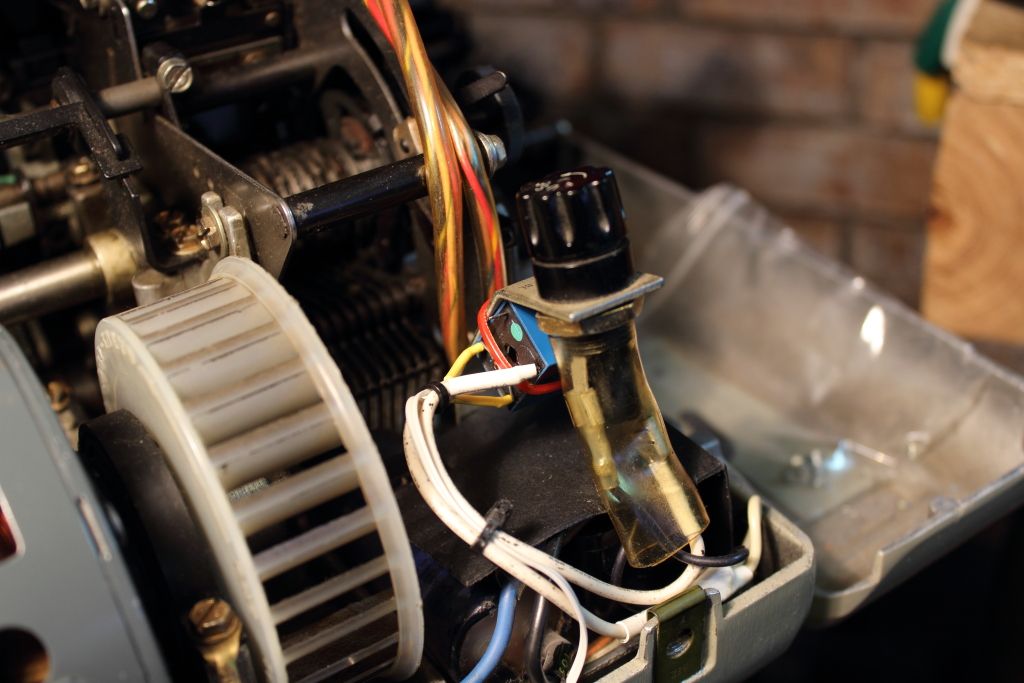
Using Automatic Answer on a model 33 is generally a bad thing. The sole purpose of the feature is to let you receive calls while you are not near the machine but doing so means leaving the teletype whirring away for hours at a time. Possibly days. The model 33 isn’t designed for constant use. Just two hours a day on average. If we could turn the motor off in the meantime though we could in theory leave the machine alone for as long as we wanted. The solution was to use the AA indicator LED we routed into the machine earlier. Because we don’t need the keyboard to toggle it on or off, when AA goes active a relay installed before the motor will energize, open and turn the motor off.
When someone calls that LED blinks, so a capacitor is used to keep the relay active over these brief lapses. Once the modem lights the CD LED we can then use basic logic to allow the relay to close and the motor to start and then after the call completes the relay will again open and turn the motor back off until you press LOCAL again to turn automatic answer off or turn the entire machine off.
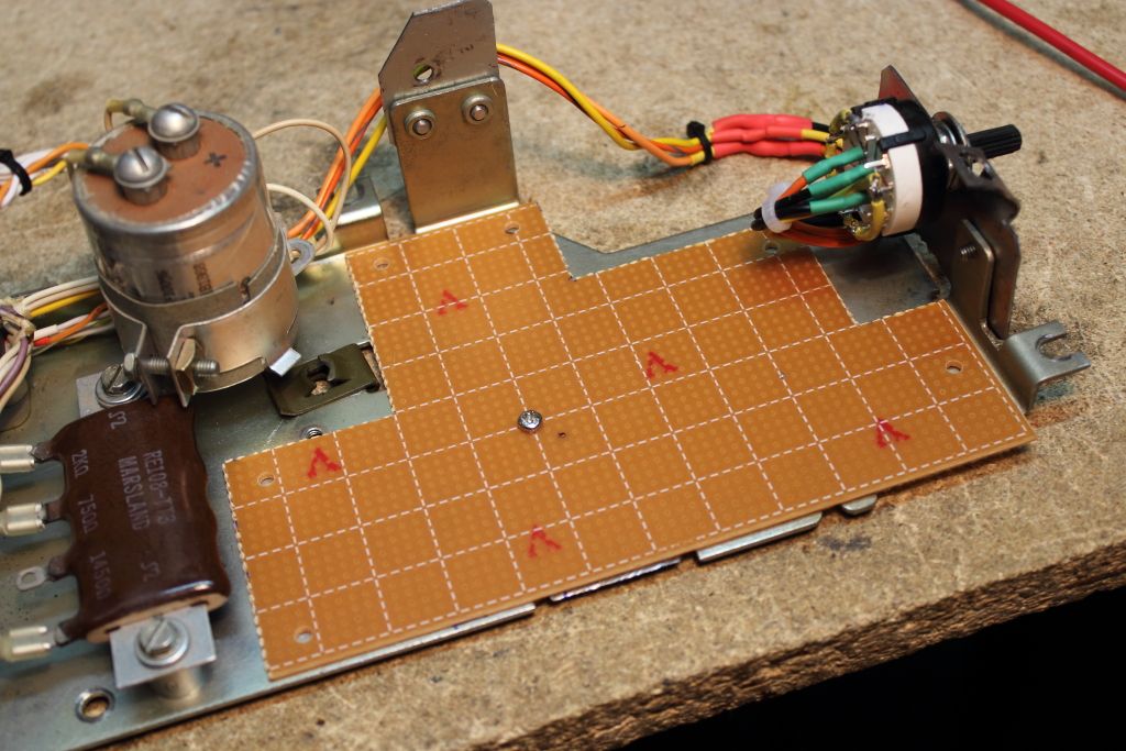
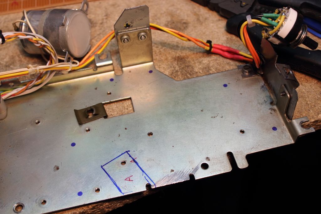
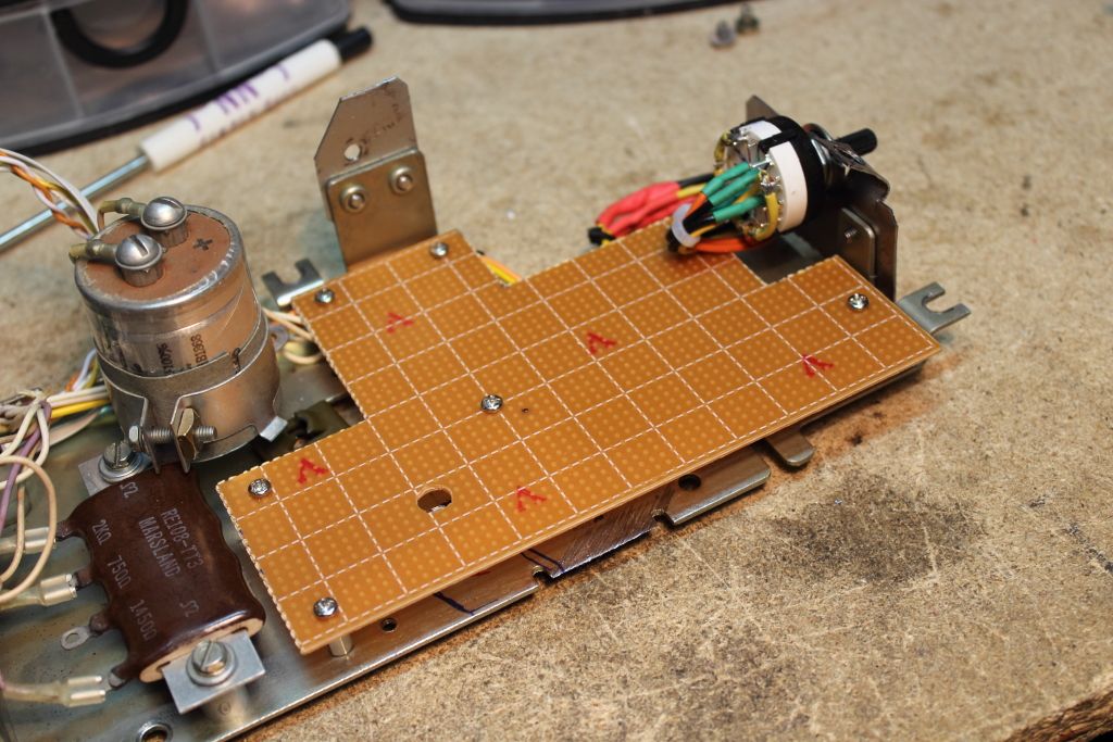
Now came the part I feared most. Board construction. I first had to relocate the large capacitor to make a little more room inside, then I was able to template out a PCB that could use the most space as it could on the CCU. Then it was scored and snapped.
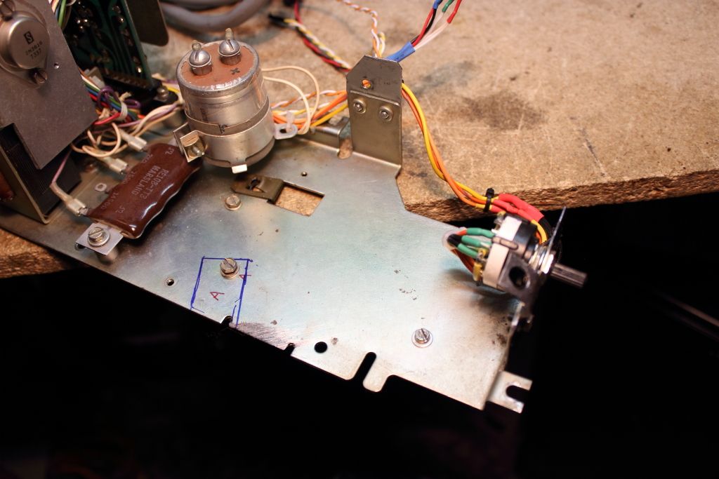
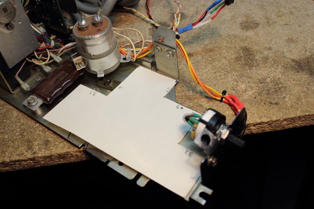
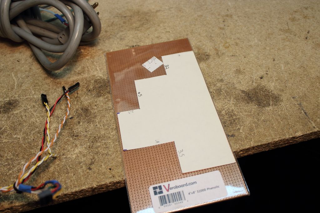
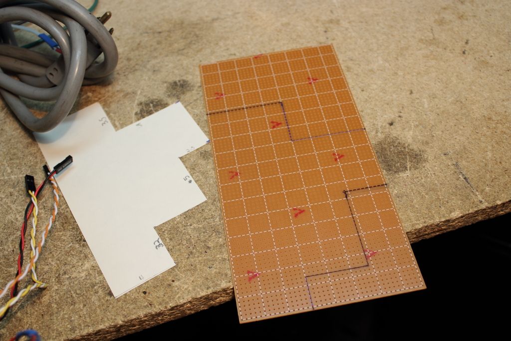
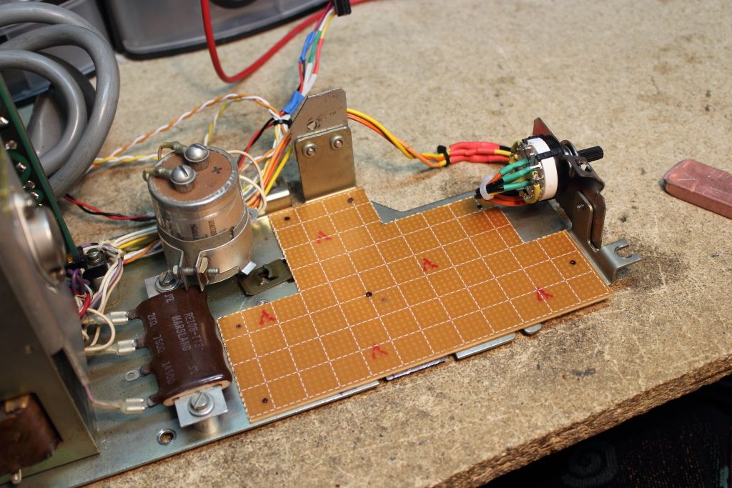
I determined a few good locations to add screw standoffs then drilled them out. Then using the board itself as the template I marked on the CCU where each hole would be and drilled, tapped and threaded in the standoffs without any alignment problems.
****CLICK HERE FOR PART 6****
Continuing with me wanting to make everything pluggable in some fashion for the sake of making work on it easier as with all my connectors so far I had been using connectors typically found to plug in the LED’s and switches on the front of a PC. Making all the lamps and switches on the front work with one connection required me to source out an old Dell machine.
Using Automatic Answer on a model 33 is generally a bad thing. The sole purpose of the feature is to let you receive calls while you are not near the machine but doing so means leaving the teletype whirring away for hours at a time. Possibly days. The model 33 isn’t designed for constant use. Just two hours a day on average. If we could turn the motor off in the meantime though we could in theory leave the machine alone for as long as we wanted. The solution was to use the AA indicator LED we routed into the machine earlier. Because we don’t need the keyboard to toggle it on or off, when AA goes active a relay installed before the motor will energize, open and turn the motor off.
When someone calls that LED blinks, so a capacitor is used to keep the relay active over these brief lapses. Once the modem lights the CD LED we can then use basic logic to allow the relay to close and the motor to start and then after the call completes the relay will again open and turn the motor back off until you press LOCAL again to turn automatic answer off or turn the entire machine off.
Now came the part I feared most. Board construction. I first had to relocate the large capacitor to make a little more room inside, then I was able to template out a PCB that could use the most space as it could on the CCU. Then it was scored and snapped.
I determined a few good locations to add screw standoffs then drilled them out. Then using the board itself as the template I marked on the CCU where each hole would be and drilled, tapped and threaded in the standoffs without any alignment problems.
****CLICK HERE FOR PART 6****