• Please review our updated Terms and Rules here

Building the world's (currently) smallest RX02 emulator

hideehoo

Experienced Member
Joined
Aug 4, 2015
Messages
129
Location
Prior Lake, MN
Yet another spin on AK6DN's RX02 emulator project. This was my original idea that I shelved after deciding to build the standalone LCD/button version. After seeing AK6DN back at it with his new SMD design to optimize of automated assembly, I decided to finish this one up and add a couple more features along the way.

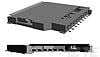
Instead of a standard Arduino Mega 2560, this one uses the smaller Mega 2560 Pro Embed board available from your favorite China based sellers. I also was able to squeeze a fullsize SD card slot on it (less fiddly than the micros, and you can always use an adapter) and added buttons to trigger a ReINIT and hard reset so you don't need to unplug the power if something hangs up.

Parts are on the slow boat from China currently, so it will be a few weeks before it's fully assembled and tested. I'll make all the design files on Github public once that happens.

1666288503400.png
1666288546218.png
1666288635561.png


1666288063174.png
 
That's cute and I want one,let me know ify ou make a batch and have spares to sell.
but...
If you wanted to make it even smaller, you'd have to make it a lot bigger.
That is, a cool thing would be if the interface board was on a flip-chip format. That way it could just live in the backplane someplace. For bonus points one could use the backplane for power, using jumpers to determine if it were in an OMINBUS, QBUS, or UNIBUS backplane.

You can effectively do that now with the current RX02 emulator design.
Build a dual size full height UNIBUS/QBUS/OMNIBUS carrier board that only grabs +5V/gnd from the backplane (with jumpers as necessary).
Put footprints for a Mega2560 (inverted) (or a Mega2560proEmbed) on the carrier, and a footprint for the RX02_emulator shield.
Thru hole headers / sockets as appropriate.
Wire the necessary signals together in the carrier board (the emulator uses just 20) and supply power/ground to each board footprint.
Orient the boards for usability (ie, probably the emulator microSD slot facing up near the card top edge).
The microSD adapter could even be removed from the emulator and remoted as a separate install (just five wires plus +5V/gnd).
Plug them all together and insert into backplane.
My guess is it might be thin enough to use up just a single slot, worst case is the next slot over needs to be cleared.
By my measure, the required clearance for either the RX02_emulator or Mega2560 would be 9/16" height off the baseboard.

I have no personal need for such a configuration, all the slots in my 8m, 11/44, and 11/34 are filled with boards.
 
Last edited:
Or if you are going to do a baseboard anyway, just plop down the circuitry for the RX02 emulator on it as well.
Nothing high speed or critical in the main logic. Probably only the SPI bus to the microSD card needs some careful layout thought.
Then the embeddedPro version of the mega2560 makes more sense as the compute engine.
I am finding that getting info (specifications, manual, pcb dimensions, etc) on the Mega2560 embedded pro is not very easy.
Seems to be lots of sellers (Amazon, Aliexpress, etc) but all are clones of what I think is a "robotdyn.com" design.
But that site is failing to load (gets a redirect error). I guess it is not an official Arduino design but rather one that clones the Mega2560 to a new form factor.
 
While we are redesigning the universe I have a silly idea. Why not combine the logic on Roland's M8357 board using surface mount components and the RX01/RX02 emulator into a single PCB. Actually there is not very much on the Mega2560 board, so one could add those components too directly on a all-in-one PCB. No cabling required. 🤪

Quite likely JLCPCB can manufacture this board for very little money. :)

Of course "changing floppy disks" in an 8/e in a rack with the lid closed becomes painful. :(

... or do it all in an FPGA. 🤪
 
I am finding that getting info (specifications, manual, pcb dimensions, etc) on the Mega2560 embedded pro is not very easy.
Seems to be lots of sellers (Amazon, Aliexpress, etc) but all are clones of what I think is a "robotdyn.com" design.
But that site is failing to load (gets a redirect error). I guess it is not an official Arduino design but rather one that clones the Mega2560 to a new form factor.
See the table of reference documents at the bottom of: https://web.archive.org/web/2021101...c==0G-00005641==MEGA-PRO-CH340GATmega2560.pdf
 

Attachments

  • MEGA-PRO-CH340GATmega2560.pdf
    30 KB · Views: 6
While we are redesigning the universe I have a silly idea. Why not combine the logic on Roland's M8357 board using surface mount components and the RX01/RX02 emulator into a single PCB. Actually there is not very much on the Mega2560 board, so one could add those components too directly on a all-in-one PCB. No cabling required. 🤪

Quite likely JLCPCB can manufacture this board for very little money. :)

Of course "changing floppy disks" in an 8/e in a rack with the lid closed becomes painful. :(

... or do it all in an FPGA. 🤪

Too much integration. Does nothing for PDP-11 QBUS or UNIBUS systems. Or PDP-8 chip based platforms like VT78 / Decmate.
 
Finally had some time to assemble my v1.0 boards I had made up for this. Good news is everything more or less worked first try, but I did figure out why this and my previous design with the LCD menu required a manual ReINIT before the controller card would see it, turns out I failed to pick interrupt enabled pins for the Init and Run (although Run doesn't currently look interrupt enabled in the code) signals when I remapped everything to better fit the PCB designs. Cut some traces and bodged some wires and all good, so I'm going to do a v1.1 of this before I release the design files and gerbers if anyone else wants to build one.

Couple of glamour shots, including a size comparison to my other design built on a full size Mega2560. Yes, that is an H11.

PXL_20230312_234025832.jpgPXL_20230312_235230622.jpg
 
I see in your BOM that you used the TE 2041021-3_2, which is no longer available from the (or at least my) usual suppliers:


Where did your obtain yours, or where could I obtain some for myself :->?
Do you have a workable alternative?
 
I see in your BOM that you used the TE 2041021-3_2, which is no longer available from the (or at least my) usual suppliers:


Where did your obtain yours, or where could I obtain some for myself :->?
Do you have a workable alternative?

It's a common footprint for the various Chinese "long body", "non popping", or "push pull" SD sockets. I usually grab mine from Aliexpress


but also available from several different manufactures on LCSC


I believe a Wurth 693063010911 or AMP GSD090012SEU will also sub when I was comparing footprints years ago if you want something domestically.

 
Back
Top