• Please review our updated Terms and Rules here

C64 Tape interface / adapter - New Project

Merlin

Experienced Member
Joined
Apr 23, 2008
Messages
290
Location
Manchester, UK
Hi,

I thought you guys might like to know about a project I'm working on to produce an updated and upgraded version of Markus Brenner's C64S interface. Markus no longer has the Gerber drawing for his original and recent events have allowed us to improve on his original unit.

An old home made 80s standalone tape-to-tape duplicator was bought by Arkanoid at Lemon64 and he posted photographs. I've been studying these and I think I've managed to reverse engineer it and combine it with Markus' original C64S interface.

The new unit should work in three modes as follows.

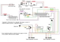
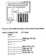
1. Standard C64S mode to allow TAP files to be written back to tape from a PC via the parallel port and using programs like MKTAP or TAP2WAV.

2. Downloading of D64 files to a Commodore 1541/71/81 disk drive via a 6 pin DIN IEC interface.

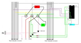
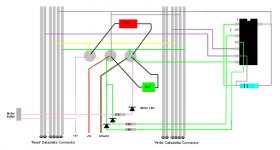
3. Stand-alone tape duplicator mode, to allow 1:1 backup of original tapes with little or no loss of signal quality, using two datasette units.

The unit also incorporates LEDs to indicate data transfer to tape either directly from from the PC or from read / write datasette units; this will be useful to indicate when data download or backup is complete. It has been redesigned to allow for the use of either a cheap external mains power supply for PCs without joystick ports, or to use a separate adapter to connect to Joystick ports for the 5v supply.

The project and schematics are here:-

http://www.amibay.com/viewtopic.php?f=88&t=2742

Comments and suggestions are welcomed and I should be building a prototype unit to test in the next week or so. If anyone is interested in purchasing one of these units as the C64S is no longer made, please let me know either here or at AmiBay.

If there is enough interest, we will get the PCB drawn up in Eagle and look to get some boards professionally made.
 
I have interest, primarily for the purpose of emulating a Datasette using a PC so I can read tape programs onto a physical C64. I already have an adapter for getting things onto disks, so while that's quite a useful application, in my case it isn't.

Very cool project.
 
Well, I do see a few problems. A 7416 is like a SPST switch to ground, so there is no + voltage coming out of the outputs to drive the LEDs, transistors, or the various inputs. Also, 10K is way too high for an LED ballast; depending on the LEDs, 100-300 would be more like it.
Finally, I don't know how the 7805 will work with only 5V input if you tap power from the MIDI (or mouse) port.

Forget the transistors (They look like the wrong type and connected backwards anyway) and connect the LEDs and resistors between the '16 and +5V instead of ground, and you should be OK as long as they draw <40 ma; if they're on when you want them off, run them through another '16 buffer.

You *might* also need a pull-up resistor on the write output; I don't see one in the datasette, and the interface is not usually done with open-collector drivers.

Not necessary of course, but it might be handy if it were bidirectional, i.e. either drive can read or write; you wouldn't have to worry which is which, and you could also make two tapes simultaneously if the PC is the source.

Something like this is also handy sometimes for transferring stuff between computers (with the appropriate connectors of course).
 
Last edited:
@ MikeS

Hmm... on an earlier schematic I drew, I just took the LEDs straight off the 7416 via a resistor to ground and was advised that this may draw too much current and pull the tape signal down, hence Zetr0 pointed me in the direction of the 2N3109 NPN transistors to feed these.

I added the 78L05 to compensate for an unregulated mains adapter, to ensure that only 5v reaches the main board. Many people don't realise that a cheap unregulated mains adapter on low load can reach a lot more that 5v; I have seen them ramp as high as 12v!!

As I said in the thread at AmiBay, I haven't done anything like this in a very long time and would not want to wreck vintage equipment by making a mistake; could you possibly sign up at AmiBay and give me some pointers as to where I am going awry with the design?

I would really appreciate this as I feel I am so close to cracking this project. It would probably work OK as it is now without the LEDs but I think they are a nice touch and may be useful. I plan to use mini LEDs so the current draw shouldn't be great. That being said, the LEDs could be routed through spare gates of the 7416.

Bi-directional could be good but my schematic was starting to get complicated. As far as I know, the simple datasette duplicators made back in the 80s didn't use pull-up resistors and neither did Markus' design, therefore I assumed that the datasette was an auto recording level device.

Cheers
 
Last edited:
Hello again Merlin:

The problem is that you were going to ground via the LED & resistor, but an open-collector chip like the 7416 does *not* go from 0V to +5V, it only connects or disconnects to ground just like a SPST switch; it expects the pull-up voltage to come from the load, so there's no voltage source at all for the LED (or a transistor) unless it supplies it. If it were a 7404 or 7414 for example then yes, a transistor (or another section of the 7404) would be needed if you absolutely had to turn the LED on when the output goes high, but since TTL outputs can handle much more power when conducting to ground than when they're high, loads like this LED are usually connected to +5v and grounded by the chip.

The LEDs are definitely a nice touch; I don't see any pin numbers but I think they *are* being routed through spare gates now, no?

The regulator is indeed needed if you use an external supply >5V, but it needs about 3 V difference to do its thing so if you're connected to the MIDI port there would be no voltage difference at all; I'm not sure whether it would just pass the 5V straight through. A zener diode and small capacitor might be simpler and just as effective.

If the original used a 7416 without pull-up resistors and worked, then no argument. It's not really a good idea from a noise point of view but you do usually get away with it.

You should just be able to connect the two write lines together in order to be able to create two tapes at once from a PC; the fact that one would be writing to itself as well as the other when copying wouldn't matter since the reading drive is not listening on its write line.
To be able to read from either one you'd probably have to use the two remaining buffers to 'wire-or' the two signals and invert them again.

Actually, it's simple enough that I just might cobble one together myself just to make sure I'm not spouting gibberish; I just have to find an old PCB to cut the connectors from.

Put it together on a breadboard and instead of connecting it to real computers just touch the various inputs to ground or 5 V with a short wire and see for yourself what happens to the LEDs and the outputs; nothing like "hands-on.".
 
OK, let me explain.

The LEDs are intended to be nothing more than a very basic 'VU' meter, in that the signal coming from the cassette head should be enough to energise the gate and allow the LED to 'flicker' to indicate that data is being transferred. They are routed through spare gates and the transistors should provide isolation from the 5V rail. I could just as well use any other NPN transistor, e.g. BC548.

The Commodore Datasette differs from other 8-bit devices of that era in that the Datasette dealt with purely digital data, it wasn't an analog signal like the Acorn or Spectrum; it is because of this that I can use the 7416 to effectively 'clean up' the digital signal from one unit to the other.

On reflection, I see what you mean about the 78L05; I can re-jig it such that the 78L05 and capacitors only come into play when the power jack is inserted and take the normally open side of the jack to a header that can feed the parallel adapter via a header.

The unit is going nowhere near a C64 until I have tested the standalone capability and checked that this works by backing up some original tapes I have and checking if they load.

The design isn't fixed in stone and is just an idea being worked up into a prototype. I'm an industrial chemist, not an electronics designer and I am still trying to design a 1980s-style circuit, looking at it!
 
Hmm, I'm really not explaining the main problem very well...

I understand quite well what you're doing; I have 3 PETs and a half dozen C64s & VIC20s along with a pile of datasettes. Many years ago I built something similar to connect some of these computers together, which is essentially the same thing that you want to do, without the PC connection and with 5V available (and reversed of course), i.e. Tape1 OUT > Tape2 IN, and (in my case) Tape2 OUT > Tape1 IN. All it takes is a 7404.

What I think you're all missing over there is that when the output of an open-collector chip like the 7416 goes "high" it does *not* output any voltage; it just disconnects from ground like an open switch or relay. If you connect one side of the LED or transistor to ground and the other end to the output of the 7416 there is no voltage anywhere to light the LED or whatever; you're either connected from ground to ground or from ground to an open circuit (hence the name "open collector").
The LEDs are isolated from the 5V all right; they're never connected at all ;-)

7416 Input=high: GND---LED---Resistor---GND
or
7416 Input=low: GND---LED---Resistor--- (no connection)

Either way, there's no current flowing anywhere, so instead you connect the LED to +5V and wire it like a light switch in your house:

Input=high: +5V---LED---Resistor---GND (LED=ON)
or
Input=low: +5V---LED---Resistor--- (no connection, LED=OFF)

You don't need the transistors, although if you did use 'em you'd need PNPs; you *might* have to use an extra section of the chip though, to invert the signal if the LED is normally on and you want it off.

The 7416 doesn't really 'clean up' the signal since it's digital anyway; the main reason you need anything at all is to invert the signals because read and write are opposite polarities, and to drive the LEDs. If I were building it I'd use a 7414 which does "clean up" the signal and is in fact what the CBM cassette deck uses IIRC, and that's also what you'd use if you were interfacing to an audio cassette deck or a PC sound card. However, that would need a couple of diodes to isolate the two "write" signals from each other, so that's probably why the 7416 is used.

Like I say, I could be blowing smoke; try it your way and if it works you can call me an idiot.

For that matter I had trouble understanding your explanation of the chemistry involved in the retro-brite process ;-)
A great contribution to the hobby (and other applications no doubt); Thank you!
 
Last edited:
I was so far mainly just looking at the problems with the LEDs, but I think I see another one; namely, you have pin 2 of the '16 connected to pin 3 of the PC; aren't they both outputs? That could be a problem if pin 1 of the '16 should go high as I suspect it might if only one drive were connected.

But I could be wrong...
 
@ MikeS

To save us posting back and forth, could you please edit my schematic to the way you think it should be configured, so that I can more easily follow what you mean? I do so want to get this right.

Thanks
 

Attachments

  • Upgraded C64S version 1.1 - draft.jpg
    Upgraded C64S version 1.1 - draft.jpg
    20.2 KB · Views: 2
@ MikeS

To save us posting back and forth, could you please edit my schematic to the way you think it should be configured, so that I can more easily follow what you mean? I do so want to get this right.

Thanks
Nah, too easy ;-) Besides, I did draw a schematic ;-) But it appears that I'm not very good at explaining open-collector TTL...

In the time you (we) have spent discussing this here and over there you could have breadboarded it, debugged it, and built a half dozen ;-)

Ignore all the suggestions (except to breadboard it and get on with it); in your first version 1.1 (without transistors) change the resistors to ~200 ohms, turn the LEDs around, and connect them to +5V instead of ground. If it turns out that they're on when they should be off, put one of the spare buffers in between. Try it out. Why two LEDs BTW? Which read and write are the LEDs supposed to indicate? Seems to me they'll both just blink together since when something's reading something else is writing, no? And maybe we'll need to keep the two read signals from interfering with each other.

I'd need to know what the idle polarity of the various outputs is (and fix errors that *I*'m probably making) before I could give you a final schematic. How would I edit it anyway?

I'm curious though: you say the original worked without pull-up resistors; is that circuit on line anywhere?
 
Last edited:
Markus Brenner's original C64S unit looked like the black and white diagram attached, although this unit only drove one Datasette unit.

Also attached is my best shot at deciphering Arkanoid's photographs of his unit as posted on Amibay. I haven't included the power supplies, as I was only interested in the main circuit. This design seems to supply 5v to the LEDs and is probably pulsing the line to ground to light the LEDs.

I can't guarantee the resistor values as the colour codes were hard to make out from his photos, even after enhancement in Photoshop. I have asked him to check my interpretation of the circuits inside his unit and let me know the values or codes of the resistors and capacitors used.
 

Attachments

  • pinout.jpg
    pinout.jpg
    10.9 KB · Views: 1
  • Arkanoid.jpg
    Arkanoid.jpg
    72.4 KB · Views: 1
Hello again:

Boy, for a project using 1/2 an IC and two LEDs this is sure taking on a life...

I didn't really want to butt in, just to warn you that most or all of the suggestions on the "other" forum were wrong and leading you off in wrong directions. As you can see from Arkanoid's unit, a 7416 has more than enough drive current for an LED and you don't need any transistors, even if they were the proper polarity and connected properly unlike the ones suggested; also there is a pull-up resistor as I suspected (not needed in Brenner's circuit since there's no 7416), and I think you'll find that the LED ballasts are a lot less than 10KOhm.

The Arkanoid schematic looks close; I think you've got the cassette connectors backwards and the read & write LEDs' polarity reversed; there's also something wrong at the IC; I think the connection to pin3 should probably be to pin2, but I don't know what you'd connect to pin3 instead; like I say, the read and write LEDs will just blink in unison anyway, although out of phase. Actually, your original circuit was pretty good except for the LEDs being connected to ground instead of 5V (and the missing resistors of course).

To add a connection to the PC's input is trivial; just connect to the existing read line; the output is a little trickier since you'd have two signals fighting each other, so you'd need a couple of isolating diodes or use two more sections of the 7416.

Build the prototype and play with it! That's the best way.
 
Yeah, I realised that the cassette connector was reversed and have corrected that in the schematic now, as attached.

I have re-checked the photos and pin 2 of the 7416 is definitely NOT connected; it seemed weird to me too.....

That schematic took a lot of coffee, paracetamol and Photoshoppage to get there!

I haven't designed circuits for over 20 years so I am very rusty, mind you, I could talk about bromine free radical reactions all night long......;)

This is keeping my grey slush working, so it's all good practice for me. Thanks for the pointers, I'll switch the LEDs around and have a play once I get the parts in.

By the way, for those that need the information, the Datasette edge connector details are:- track width 2.1mm, gap between tracks 1.7mm, slot width 1.7mm, slot depth 9mm. All of these were measured on a breadbox 64 main board using a micrometer.
 

Attachments

  • Arkanoid.jpg
    Arkanoid.jpg
    74 KB · Views: 2
Last edited:
Well, pin3 is an input, so I dare say that LED isn't going to light even if you do turn it around ;-)

I think you would have been better off starting with a blank sheet of paper ;-)
 
That schematic took a lot of coffee, paracetamol and Photoshoppage to get there!
Might be time to try one of the free schematic capture tools out there. Kicad is a good one. It takes time to get used to, but you'll quickly win that back in time spent farting around with Photoshop ;-) This from the guy who used to draw schematics in PowerPoint...

By the way, for those that need the information, the Datasette edge connector details are:- track width 2.1mm, gap between tracks 1.7mm, slot width 1.7mm, slot depth 9mm. All of these were measured on a breadbox 64 main board using a micrometer.
A.k.a. a standard 0.154" edge connector.

Look forward to seeimg the prototype!
 
Right; I'm going to build the prototype without the LEDs, so that I can test the data transfer capabilities and make sure that nothing has gone screwy there. I am keeping it as one read and one read/write connector, so that for general use connected to a PC you would use the read/write and you would only need the read one for duplicting tapes.

Once I've proved all of the tape transfer side works (I don't have a 1541 but I haven't changed that side of things, so it should still work OK), I will try adding an LED to the read/write connector side (the one you really need to know is working).

I am changing the power feed such that the 25-way adapter connects via a 2-opin header to the power lines and by changing the polarity of the power socket, I can arrange things such that the external supply feed the normally open contact of the jack socket and only powers the 78L05 side of things when the contacts are closed; it may need a diode in there, but I think it will work without.

@ Cosam

I have tried doing the schematics in Eagle, but how the Germans managed to take all of the fun and intuitiveness out of that program leaves me in awe and it was doing my head in; it's like it was written by Vulcans.... ;)
 
Ah yes, those Krauts; they do have their ways... (I can say that, I've got German blood in my veins ;-)

Well, you could still tie the two cassette write lines together so that you could make two copies from the PC if you wanted.

I think you may find that you'll have to isolate the PC and cassette "reads," in which case you could have two LEDs to indicate the data source; read and write don't really make sense because they'll always be on together.

Finally, if you have a <5dollar store nearby, cheap *regulated* 5V @ 2500-3000 mA switching adapters are pretty common these days, and would save you the regulator and avoid the complexity of a separate connection for PC power. Might be worth a zener diode though, in case an unregulated one is plugged in inadvertently.

I may really have to build one of these myself after all this R&D...

@ Cosam:
Was it you who asked for a scan of the docs for one of the PET utility ROMs (can't remember which one)?
 
Last edited:
The problem is, not all uber-cheap power supplies state if they are regulated ones or not, and from my experience, most Chinese-made ones tell lies on the packaging. I wouldn't trust them and would rather have the security.

Can you please explain the zener diode and how it would be put into the circuit? If it means I can do away with the 78L05 and caps, I'll go that route.

Sorry about this, but my specialist subject is chemistry, not electronics!!

Edit:- I have just been looking into these and the one I think I need is a BZX79C5V1, does that sound like the right one? I would welcome your guidance as to the value of the resistor for the shunt.

Thanks
 
Last edited:
The problem is, not all uber-cheap power supplies state if they are regulated ones or not, and from my experience, most Chinese-made ones tell lies on the packaging. I wouldn't trust them and would rather have the security.

Can you please explain the zener diode and how it would be put into the circuit? If it means I can do away with the 78L05 and caps, I'll go that route.

Sorry about this, but my specialist subject is chemistry, not electronics!!
----
You can usually tell from the weight and rated current, but good points all the same!

Zeners come in different voltages (and max. currents of course); essentially, if you reverse-bias it (i.e. put voltage across it in the non-conducting direction) then if that voltage exceeds its rated voltage it will clamp it at more or less that voltage unless the difference is so great that the excessive current releases the magic smoke. Usually you put it across the supply with a small resistor or fuse between it and the supply.

+5V ----- Fuse/Resistor ----T----- > Load
|
---
/\ 5.1V Zener
|
GND

A cap or two might still be advisable in any case, especially since you're also powering a DC motor.
--
Hmm, looks like leading spaces disappear; the zener should connect at the T

Considering that you're powering a motor or two as well as the IC, using a resistor and Zener might not be practical for regulation since the motor current(s) would drop the voltage too much through the resistor; I meant it more as over-voltage protection with a fuse, especially with an externally regulated supply.
 
Last edited:
Back
Top