• Please review our updated Terms and Rules here

Can a heat gun kill an IC, even if it was never directly in the path of the heat?

Horizontally, it looks like it repeats every +1 and +8 and/or -7 and -8 words. Vertically, it looks like +7 and +8... I'd start with the 8, which would relate to A3 or RA3F from the schematic. It looks like RA3 is generated by IC 2F, a 74LS257, or the 74AS253 at 3F (depending on the state of the DMA signal) and becomes RA3F after passing through a 47 ohm resistor in RP2...

I looked up the one schematic for these machines that's reasonably easy to find and... ugh. Just ugh. Maybe there's no more efficient way to do what they needed to do but that mix of 1-of-2 and 1-of-4 multiplexers to switch between the CPU, video, and audio buffer addresses is kind of a nightmare...

That said, from looking at this and comparing the mod instructions to the memory maps for the 128k and 512k macintoshes the theory behind the actual mod should be pretty simple, right? Essentially all it should be doing is taking an NC line to the memory sockets, connecting it to *one* of the outputs on the added 'AS253, and multiplexing that line between either CPU A17/A18 (if the CPU is selected) or just outputting a "1" if video or sound is selected, right? (The memory map I found suggested that the video and sound buffers are always located at the highest point in memory on all the original toasters, so outputting a "1" on these lines when "DMA" is selected should kick them up to the very top of memory, right?) If that's all it's doing then it's genuinely difficult to see how the damage that's clearly been inflicted to cause this corruption could have come simply from the installation of the mod components themselves.

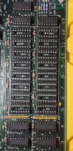
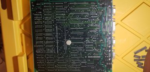
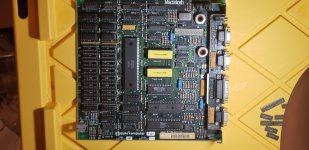
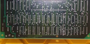
Are there pictures of the current state of this board posted anywhere?
 
I'll take some pictures later today. If you want, I can remove the memory from the sockets I put in.

What makes this so odd is that my soldering skills are impeccable.

Like, legitimately. It's not an inflated ego.

If you look at some of my past projects, you'd think that it was done-from-the-factory. I always use flux, leaded solder (stay away from me with that silver solder...), and unless the component is being difficult, I never dwell too long on a pad or via.

It's why I was able to put the memory sockets in my Sanyo MBC-775 without damaging any traces. (And the only problem I'm having with that particular computer is the memory not counting past 256k.)
 
Last edited:
Correction to my last post: It is A2, not A3 that appears to be stuck. The difference is 8 bytes, but the memory is word-addressed, so that's only 4 words...

I kept getting thrown by that distinction myself; looking at the 128k schematics I was like “wait, A16 is multiplexed onto DRAM A7, that‘s not right…” until I reminded myself that on the 68000 there is no A0.
 
All right, here are my pictures.

NOTE: If you find what looks like damage on the board (Namely, on the bottom, two chips in from the left, around the 1983-1984 part of the Apple copyright branding text), I went back and re-checked it. It's just dried spots of flux that I forgot to clean up/chip off.
 

Attachments

  • 20220911_131102.jpg
    20220911_131102.jpg
    1.2 MB · Views: 8
  • 20220911_131148.jpg
    20220911_131148.jpg
    1.1 MB · Views: 11
  • 20220911_131205.jpg
    20220911_131205.jpg
    1 MB · Views: 10
  • 20220911_131125.jpg
    20220911_131125.jpg
    1.1 MB · Views: 10
Last edited:
That's a mysterious 820-0086-F board. Not much information out there about them. HOWEVER, I do notice a jumper, W1, which is labeled "128K ONLY." Have you tried removing this jumper? There are some other parts that are labeled "512K ONLY" that are installed, but the resistors are blue whereas all the other resistors on the board are brown, so it's not clear that they are factory installed... But try removing W1 and see what happens.
 
I notice also that the chips at F3, F4, G3 and G4 are 74LS253, not AS253 or F253. The LS parts are not fast enough, so that can cause problems. There's also something at G13 ("512K ONLY" section) that should be an AS253 or F253, but I can't read the markings. But when I zoomed in to try to read the markings on the chip, it does look like W1 has been removed and what I thought was a jumper is just a line on the silkscreen. But I still want to know if those "512K ONLY" parts were factory installed or if you installed them?

Edit: OK, I saw this, which I missed the first time through, in the Dr. Dobbs PDF - I assume these are the instructions you followed:

MacMod.jpg

So at this point you need to replace those LS chips with the proper AS or F series parts and report back...
 
Last edited:
Oh?! I took out some of the logic chips (Including the 253s) some months ago and replaced them with new ones just to see if they had failed.

Didn't help.

I will take a look at the AS/F series chips, though!

And yes, I did follow those directions, adding in the custom parts.
 
Was the behavior exactly the same before you replaced those 253s, or did it change?

Unless you have specific reason to think you busted something it would probably be better when troubleshooting a failed upgrade to limit yourself, at least initially, to reversing whatever you did and see it that rolls it back. Shotgunning is a strategy... but it usually doesn't work.
 
It was the same. I kept getting the screeching, and a corrupted screen.
Wait. Just. Stop.
The question he asked was "Was the behavior exactly the same?" We have no idea because you haven't posted a screen shot of that iteration.

You added a chip at G13 as part of the upgrade. Was that originally an AS or F part, or was it always an LS (assuming that's what's in there now, as that's the one that's impossible to read)?

Again, there could be multiple problems, but the wrong chips are definitely a problem. Put the correct chips in and if it's still not working at that point, post a screen shot. Then we can proceed based on what we see. It may be appropriate at that time to roll back the changes (but leaving the sockets in place) to see if the problem occurred when adding the sockets or if it's something related to the 512K mod. If there is one or more stuck address line caused by the desoldering & adding sockets, then a problem will still be evident with the 64K chips installed...
 
FINALLY. Mouser is slow with its economy shipping. (7-10 days my ear...)

Okay, the situation has changed. Now I'm getting the power supply fluttering as described in the Dead Mac Scrolls, rather than a startup tone and a picture. I checked the voltage on the VR56 voltage pot, but I can't turn it up higher than a volt or so. (The pot mechanically doesn't go up higher) It's also fluctuating all over the place.
 
Yes you have to use 74AS/74F, they need that extra speed over 74LS. And I didn't realize there was a 128K version of the "Fat Mac" motherboard, mine back in the day was an original 128K and just had the short row of holes.
 
I get something odd, other than the resistance value described for the rectifier at CR20, as described in the Dead Mac Scrolls. Is 60 Ohms normal, or should it be 30, as described in the guide?
 
I had those exact symptoms about three weeks ago. Turned out to be excess dust in heatsinks/fans/motherboard slots. A thorough clean and all was well.

Kev
 
Back
Top