• Please review our updated Terms and Rules here

Cbm 2001 Pet strange boot

Have you read the instructions for the RAM tester?

First rule of electronics - don't plug ANYTHING into ANYTHING unless you know that the parts are compatible- hence all the wasted time and effort with the 2532 and 2732 saga.

In that case, no damage was done. In another case, you might not be so lucky - especially with +12 and -5 Volts around the 4116s.

Look up the data sheets on the parts and check the pinouts, voltage levels and (if nothing else) the part description text.

Dave
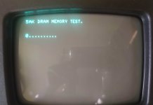
With 4164 tester works fine but with this equivalent 4116 not...maybe not compatible with this tester....maybe also with Pet????? I am des....
 
What did the sales information say?

In the manual there should be a list of devices that are compatible with the unit.

I know some RAM testers will not test 4116 (or lower) because of the triple voltage rail requirement. They will only test 5V devices - hence 4164 and above.

Most of the units I have seen that test 4116 and 4164 (etc.) have two IC sockets for this reason.

If you then plug a 4164 into the socket for a 4116, it dies a horrible death!

Dave
This Ram tester works with 4164 and 4116, i have only one socket but i have a little bridge to set correct Ic.
Maybe can tests only 4116 and not equivalent... i am desp
 
Thanks for the kind recommendation to my gadgets but I'm not convinced the OP really needs it at this stage and also there are other boards available and I don't want to use this forum as a sales channel. :)

Seems the RAM and RAM refresh and addressing needs investigation and I would be tempted to leave the PET on for a prolonged period and see if anything fails!
 
This Ram tester works with 4164 and 4116, i have only one socket but i have a little bridge to set correct Ic.
Maybe can tests only 4116 and not equivalent... i am desp
If your RAM tester is working, at least some of the 4116's from the PET would be expected to test normally, or you should expect some new old stock 4116's to work in it. Obviously if your RAM tester is faulty and cannot test any 4116 as normal, you should get a new RAM tester.

How many of the 4116's in the PET have you replaced so far, just the one ?

Often it is better to do things one thing at a time. If you remove a 4116 from the PET, put a known good socketed one in and re-test the computer with the PETTESTER as well as checking the RAM you have removed in the RAM tester, this way you might not have to remove all the 4116 RAM IC's, perhaps just the one or two that are faulty. It is a shame to remove (unsolder) any non-socketed IC from the pcb if it is good and doesn't have to be removed.
 
This Pet have only equivalent 4116 ic rams...i changed only 2 ics and i replaced with new equivalent but i have always error with pettester :(
 
Tester ram now ok! found that powering it with the usb socket was not sending enough current...With smartphone power supply works fine...now i can test ic rams...maybe :)
 
I told you a few posts ago how to identify the low 16K bank of RAM. Look for the RAM that is connected to data bit 3. At the intersection of the two is your IC. Simples...
@daver2 please, where i can find data bit 3??? :(
 

Attachments

  • Schermata 2022-05-17 alle 20.59.58.jpg
    Schermata 2022-05-17 alle 20.59.58.jpg
    183.3 KB · Views: 9
Mmm maybe for Rd3 signal from 244?
Each memory IC has a one bit output, requiring 8 of IC's to get the 8 bits for the bus.

Generally though, the bits are numbered 0 to 7 (not 1 to 8 ) The zero bit is the least significant bit and the bit number 7 the most significant bit, of the value created by the 8 bit binary number.

The bit labeled 0 contributes a value of 0 or 1, the bit 1 a value of 0 or 2, the bit 2 a value of 0 or 4, the bit 3 a value of 0 or 8 etc etc that makes up the binary number coded by the 8 total bits.

Generally though the more significant 4 bits and the less significant 4 bits are represented in Hex number form, so for the byte FF, both the upper 4 bits and the lower 4 bits would be high as in 1111,1111 and if you represent that in decimal number form, by adding up the values that the bits represent, that is 255 = 128+ 64 + 32 + 16, + 8 + 4 + 2 + 1.
 
Open question. Could the lower bank be isolated using the jumper settings so that just the RAMs in row 'I' can be tested (with PETTester) independently of row 'J' thus avoiding having to desolder more chips than necessary? This would be after I6 has been socketed and replaced with a known good chip. This is the link to a very full description of the jumper settings used in the dynamic PET:


Alan
Good suggestion.

Looking at the schematic I'm not 100% sure this could be done, isolating row J of the 4116 DRAMs, just with jumper settings because it looks like the /CAS1 signal would still be active, activating row J when row I was not active (only one is active at a time due to the complimentary select logic for /CAS0 and /CAS1). But, I think it could work if the jumper settings were set for 16k and the resistor R42 was lifted and the /CAS1 signal feeding the J row of 4116's was tied high.

However, the only complication though, is that the output bits of the I & J rows, for each of the 8 bits, are tied together (hard wired), so that even if the row J was technically deactivated by tying the /CAS1 signal high, if the output of a J row DRAM IC was stuck, it would still corrupt the function of the I row IC.

One possible isolation trick could be to solder suck just the pin 14's (the output pin) of each of the 8 IC's of the J row and free up the pin in the hole and check with the meter it was disconnected. Then configure the jumpers for the 4116 16k settings to test the PET. This way the J row IC's would not have to be completely removed for testing row I
 
Last edited:
I am desperate....
I changed ram on I6 but i have same fault.... :(
Sometimes Pettester restart automatically during countdown...sometimes freezing during ram test :(
 
In this case, after 3 passes i had this fault:
 

Attachments

  • Schermata 2022-05-18 alle 19.17.32.jpg
    Schermata 2022-05-18 alle 19.17.32.jpg
    84.1 KB · Views: 5
Unfortunately I tried to insert all the roms and leave the computer on for a while ...

the cursor keeps blinking and everything seems stable .... how is that possible ??

Edit:
No...after 5 minutes is stucked again with cursor not blinking :(
 
Last edited:
Thanks for the kind recommendation to my gadgets but I'm not convinced the OP really needs it at this stage and also there are other boards available and I don't want to use this forum as a sales channel. :)
With all the help you have been on this difficult PET, and our OP who seems to be getting very frustrated, I think a RAM/ROM replacement board would be a good thing for him to try. It would eliminate a lot of questions about his memory chips without so much unsoldering. He should get your design. This PET has been a bad dog! Our OP needs to make progress or he may give up. Intermittent computer problems are nerve racking for anyone.
 
Back
Top