• Please review our updated Terms and Rules here

Cbm 2001 Pet strange boot

I've decided to play along at home... I don't have a 2001N but I do have a 2001 which shares quite a lot in common...

CaptureMeasurements.PNG

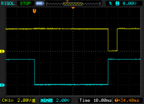
So starting with the 74154 address decoder (which is G2 on my PCB but is D2 on a 2001N PCB)... putting A15 from the CPU/NOPPer on CH2 and then moving CH1 I see...

pin 9 which is nSEL8

NewFile80.png

Can you see something similar?
 
I've been following this thread as a rooting spectator for a long while now, and Nivag's offer looks to be the way to go. The only troubleshooting advice that I could offer at this time is to hold the board about 1 to 2 feet or so (30-60 cm) above the surface, and then drop it. Not very helpful here but I have sort of 'fixed' a few things that way down through the years. Good luck! 🤖
 
I've attached a document with all the relevant pins of the 74154 decoder...

For CH2 you can use A15 which is available either at the CPU C4 p25 or also at p11 and p9 of B3, or p20 of D2 and a few other places too!

Wander CH1 around the pins of the 74154 decoder starting with pins 20, 21, 22 and 23 (the inputs) and then p1, 2,... 11, 13, 14,... 17.

See if you can recreate the traces in the document.
 

Attachments

  • PET Scope Traces - 74154 Decoder.pdf
    113.3 KB · Views: 13
I've attached a document with all the relevant pins of the 74154 decoder...

For CH2 you can use A15 which is available either at the CPU C4 p25 or also at p11 and p9 of B3, or p20 of D2 and a few other places too!

Wander CH1 around the pins of the 74154 decoder starting with pins 20, 21, 22 and 23 (the inputs) and then p1, 2,... 11, 13, 14,... 17.

See if you can recreate the traces in the document.
Unfortunately i can't see any square waves with this scope...i don't know why :(
With Ch2 and also with CH1 :(
 
Desperado, in your video in #1766, it looks to me as though your channel 1 AC / GND / DC switch is in the GND position which will disable the channel 1 input. Move it to the 'DC' position and try again.
 
Desperado, in your video in #1766, it looks to me as though your channel 1 AC / GND / DC switch is in the GND position which will disable the channel 1 input. Move it to the 'DC' position and try again.
Thanks! So this is Ch2 on UB3 pin 11:
 
Another thing I notice from the video in #1766 is that the CH1 / CH2 / DUAL / ADD switch is still in the 'CH2' position.

If you are trying to use only channel 1 this switch must be in CH1 position.

If you are trying to use only channel 2 this switch must be in CH2 position.

If you are trying to use channel 1 AND channel 2 to see two things at the same time, as Nivag is asking you to do, the switch must be in the DUAL position. So move it to the DUAL position and try again with looking at two signals at the same time to see if you can get a trace which looks like the ones nivag posted.
 
If you look at the image in #1762 or look at the images in the attachment in #1765 you will see I am using a slow timebase... 10ms/div or 20ms/div. Your video in #1766 shows 1us/div... that is 10000 times faster than mine! SLOW DOWN dude!

The PET is a very slow machine... 1us is nothing!

(Also... not sure about the x10 Mode button... sounds like that should not be depressed?)
 
Last edited:
If you look at the image in #1762 or look at the images in the attachment in #1765 you will see I am using a slow timebase... 10ms/div or 20ms/div. Your video in #1766 shows 1us/div... that is 10000 times faster than mine!
im desperate because if i set to 10ms i can't see the waveform!!!
(Also... not sure about the x10 Mode button... sounds like that should not be depressed?)
is not pressed!!
 
Welcome back Nivag.

Just to remind you desperado, you have already performed this test back in post #1,662.

In this case you were measuring BA15 on channel 2 as a trigger and A3/11 (/SEL8) on channel 1.

If you noted down the oscilloscope settings that you used for this test in your notebook, you should just need to repeat the same test configuration.

This test setup can be used for all of the /SEL outputs of UD2 (not just /SEL8 as we were using back then).

For Nivag’s benefit, I think we have already demonstrated (with the NOP machine) that UD2 is working. I think we did have a faulty output and UD2 was changed. Nothing wrong with double-checking the results though. The more practice for the apprentice the better...

What I was trying to do was to move on and look at the data bus when the UD9 ROM was enabled to check for any bus contention or missing data lines. As /SELF appeared to be there, then the ROM should be selected and the only thing left is a dicky data bus preventing the ‘noddy’ test program from running correctly.

The effect we saw was that the test program was ‘escaping’ from the ROM.

Dave
 
Last edited:
What I was trying to do was to move on and look at the data bus when the UD9 ROM was enabled to check for any bus contention or missing data lines. As /SELF appeared to be there, then the ROM should be selected and the only thing left is a dicky data bus preventing the ‘noddy’ test program from running correctly.

Fair enough. I was keen to document this anyway as I am working on my latest diagnostic gadget (HP Digital Signatures).

Probably worth verifying nSELF at the ROM, measuring continuity with a meter between the databus pins and the ROM and also checking for shorts between the data bus pins.

Additionally, I would either remove all the databus transceivers (to eliminate databus contention) or if they are not socketed look to scope pin 1 and pin 19 of them versus A15.

Anyway... you have more patience than me so... you have control!
 
Back
Top