daver2
10k Member
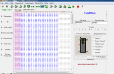
Just use your EPROM programmer first.
Load a blank 2532 into the programmer, read the EPROM into the programmer’s memory, edit the memory image (at the correct addresses) to change the FF bytes to my program, double check your work and burn the EPROM.
Dave
Load a blank 2532 into the programmer, read the EPROM into the programmer’s memory, edit the memory image (at the correct addresses) to change the FF bytes to my program, double check your work and burn the EPROM.
Dave