• Please review our updated Terms and Rules here

Cbm dual drive 3040 disk - two red lights

Desperado

Veteran Member
Joined
Nov 25, 2017
Messages
6,827
Good evening guys!!!!
I am desperate now!!!
I connected my 3040 cbm dual drive to my (now) working 2001N Pet but when i turn on, i can see only the two red leds...central led remains off :((
I followed this Sirius suggests:

It might not be the drive which is faulty.

It is not unusual for there to be a fault on the IEEE port on these old PETs and you will not notice it until you try to connect something to the port. The machine can have a faulty IEEE port and work perfectly well in other respects.

Now that the machine is working well enough to run BASIC commands there are some simple checks you can do using the BASIC POKE and PEEK commands to get an idea of whether the IEEE port is working, because the port has the unusual ability to read the state of its own output lines.

I'm sure others will be able to tell you the exact method, but for now, with the drive NOT connected, try this:

POKE 59426,0
PRINT PEEK(59424)
Result=?

POKE 59426,255
PRINT PEEK(59424)
Result =?

...Remember the address you're PEEKing is not quite the same as the address you are POKEing.

...59426 for POKE
...59424 for PEEK
 
That was quick! OK, so those results should have been 0 for the first check and 255 for the second check.


If we translate the first result you should have obtained to binary you have:


00000000


Sirius told me this:

And if we translate the first result you actually obtained to binary we have:


00100100


Counting from data bit 0 at the right hand side to data bit 7 at the left hand side we can see that bit 2 (which represents '4') is '1' instead of '0', and bit 5 (which represents '32') is '1' instead of '0'. If you add 4+32, this gives you '36'.


So the bad news is that this is telling you that you have a fault on two of the data bits on the IEEE port and the data bits in question are handled by two separate buffer ICs, UA7 and UA8. What is more, the simple check you did just now did not check the UA9 buffer, so there may possibly also be a fault with that buffer as well.


There are further checks which Dave & company can guide you through to narrow down the exact fault and rule out the 6520 - for example you can try swapping another 6520 into the UC6 position to see if that changes the results of the check but in my experience so far the cause of problems like this has always been failure of the MC3446 buffers - however they are quite expensive and difficult to find so any work you can do to prove that they are responsible for the fault before ordering replacements would be good.
 
I think that even the dual drive has some problems ... if I turn it on without connecting it to the computer, I always get the two fixed red LEDs and the central LED remains off ...
 
I've never had one of these but I am under the impression that you only get the correct LED sequence when the computer and drive are able to communicate with each other, which they won't be able to at the moment because of the IEEE port fault on the computer.

I would focus on fixing the IEEE port problem, then see how the computer and the drive work together.

Are UA7, UA8 and UA9 in sockets or are they hard soldered into the mainboard?
 
There is a standard BASIC program around somewhere that tests out most of the IEEE488 signal lines.

Dave
 
I've never had one of these but I am under the impression that you only get the correct LED sequence when the computer and drive are able to communicate with each other, which they won't be able to at the moment because of the IEEE port fault on the computer.
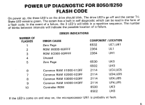
I don't know about the 3040, but in the 8050/8250, the LEDs are used for diagnostic purpose during the boot sequence even if the FDD isn't connected to the computer.

1660000276725.png
 
There is a standard BASIC program around somewhere that tests out most of the IEEE488 signal lines.

Yes, it's in one of the books available online - I'm sure ScottishColin had it because he also had IEEE port problems on top of all the other problems his machine had, and he used it to check out the whole port.

If the MC3446s are in sockets, or if they can be put into sockets, swapping UA7 and UA8 should move the locations of those two faulty bits to bit 1 and bit 6 if UA7 and UA8 are faulty as suspected. That would be reasonable proof that at least two replacements were needed and if so, I would order three and replace all of them.
 
Last edited:
I don't know about the 3040, but in the 8050/8250, the LEDs are used for diagnostic purposes during the boot sequence

That's useful info, but what I notice about it is that all of the fault codes are represented by the LEDs flashing a number of times. Desperado's LEDs are in a steady state, suggesting that the unit is not in an error condition.
 
That's useful info, but what I notice about it is that all of the fault codes are represented by the LEDs flashing a number of times. Desperado's LEDs are in a steady state, suggesting that the unit is not in an error condition.
Yes, but it also explains what is the correct behavior:
1660006903264.png

@Desperado, are you sure the problem isn't a lack of GND on the tri-state LED (or a broken LED) ? Strange that it doesn't blink, neither green, nor red...
 
Of course, if the disk electronics are a complete 'dead duck' you will probably get no LED flashing at all...

It would be interesting to check the schematics and see what the default power-up LED states would be if the processors were not running.

Of course, you have checked the internal 6502 CPUs for power, a clock and a SYNC pulse haven't you desperado?

Dave
 
A 6502 machine (of any type whatsoever) always follows the same initial way of diagnosing the problem...

Dave
 
I didn't say to check the CPU on a PET did I?

What happens if the CPU hasn't got a reset signal or a clock - or the ROMs are messed up so it is not executing instructions correctly? All of these will cause the CPU to fail.

From the schematics I have been able to find (http://www.zimmers.net/anonftp/pub/.../old/4040/2040-3040-4040_drive_schematics.pdf PDF page 3) all three (3) LEDs are driven from UE1 - so if this device is bust, or the associated 6502 at UN1 is not behaving properly - you may get the effect you are observing.

Dave
 
Last edited:
Yes, but it also explains what is the correct behavior:
View attachment 1244630

@Desperado, are you sure the problem isn't a lack of GND on the tri-state LED (or a broken LED) ? Strange that it doesn't blink, neither green, nor red...
For the 3040, all three red lights should flash and then go out. The central LED is an error light and is not tri-state as in the 8050. Interestingly I am refurbishing a 3040 as I type.

If the drive lights stay on the check then connections and also carefully reseat the chips in the white sockets. Also check you have the rom chips in the right order (sockets) On the drive MB

I have found the following article useful in diagnosing IEEE issues on the PET MB assuming your 6520 is OK. It assumes you have the drawings (from Zimmers.net) to identify which MC3446 is responsible
 

Attachments

  • 3E825DA2-4F72-405F-8CDF-314D50A9C381.png
    3E825DA2-4F72-405F-8CDF-314D50A9C381.png
    1.5 MB · Views: 9
  • DB28537B-0558-4085-8B64-E55BEE6796C3.png
    DB28537B-0558-4085-8B64-E55BEE6796C3.png
    1.8 MB · Views: 8
Last edited:
I didn't say to check the CPU on a PET did I?

What happens if the CPU hasn't got a reset signal or a clock - or the ROMs are messed up so it is not executing instructions correctly? All of these will cause the CPU to fail.

From the schematics I have been able to find (http://www.zimmers.net/anonftp/pub/.../old/4040/2040-3040-4040_drive_schematics.pdf PDF page 3) all three (3) LEDs are driven from UE1 - so if this device is bust, or the associated 6502 at UN1 is not behaving properly - you may get the effect you are observing.

Dave
I'm desperate,
For the 3040, all three red lights should flash and then go out. The central LED is an error light and is not tri-state as in the 8050. Interestingly I am refurbishing a 3040 as I type.

If the drive lights stay on the check then connections and also carefully reseat the chips in the white sockets. I have found the following article useful in diagnosing IEEE issues on the PET MB assuming your 6520 is OK.
Thanks so much sir!
 
I didn't say to check the CPU on a PET did I?

What happens if the CPU hasn't got a reset signal or a clock - or the ROMs are messed up so it is not executing instructions correctly? All of these will cause the CPU to fail.

From the schematics I have been able to find (http://www.zimmers.net/anonftp/pub/.../old/4040/2040-3040-4040_drive_schematics.pdf PDF page 3) all three (3) LEDs are driven from UE1 - so if this device is bust, or the associated 6502 at UN1 is not behaving properly - you may get the effect you are observing.

Dave
With the logic probe on cpu pin 40,i have always low signal when i turn on...also on pin 7 :(
 
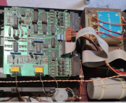
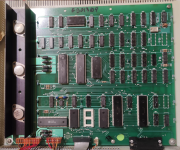
These are 3040 boards:
 

Attachments

  • Schermata 2022-08-09 alle 11.16.41.png
    Schermata 2022-08-09 alle 11.16.41.png
    1.4 MB · Views: 14
  • Schermata 2022-08-09 alle 11.16.57.png
    Schermata 2022-08-09 alle 11.16.57.png
    1.6 MB · Views: 13
Back
Top