- VCF South West - June 14 - 16, Davidson-Gundy Alumni Center at University of Texas at Dallas
- VCF West - Aug 2 - 3, Computer History Museum, Mountain View, CA
- VCF Midwest - Sept 7 - 8 2024, Schaumburg, IL
- VCF SoCal - Mid February 2025, Location TBD, Southern CA
- VCF East - April 2025, Infoage Museum, Wall NJ
-
Please review our updated Terms and Rules here
You are using an out of date browser. It may not display this or other websites correctly.
You should upgrade or use an alternative browser.
You should upgrade or use an alternative browser.
Cbm pet 8296-d black screen
- Thread starter Desperado
- Start date
daver2
10k Member
With pin 7 being LOW this indicates that the CPU is not executing instructions.
Dave
Dave
daver2
10k Member
It’s possible - but quite unlikely.
It is more likely something on the address decoding or ROM side (kernal or PETTEST ROM).
Monitor the CPU SYNC pin on startup and see if it attempts to execute any instructions at all (i.e. you observe pulses on the SYNC pin).
If you do observe initial pulses - but then they stop - time to break out the NOP generator...
Dave
daver2
10k Member
Have you got a NOP generator from begore to try?
Dave
Dave
Desperado
Veteran Member
- Joined
- Nov 25, 2017
- Messages
- 6,827
Good morning Dave, yes i have nop!Have you got a NOP generator from begore to try?
Dave
daver2
10k Member
Good morning other Dave...
I don’t know where begore came from! I meant before of course") ...
...
Is the 6502 CPU in a socket? If so, it is easy to make up your own NOP generator with a couple of 40 pin IC sockets and a few 1k resistors. I can guide you.
Alternatively, there are a couple of ROM/RAM replacement cards that also contain a NOP generator and my diagnostics. As you are repairing a lot of Commodore PET machines, I would advise purchasing one of these cards as a Christmas present to yourself! It will save you a lot of time in the long run.
Dave
I don’t know where begore came from! I meant before of course
...Is the 6502 CPU in a socket? If so, it is easy to make up your own NOP generator with a couple of 40 pin IC sockets and a few 1k resistors. I can guide you.
Alternatively, there are a couple of ROM/RAM replacement cards that also contain a NOP generator and my diagnostics. As you are repairing a lot of Commodore PET machines, I would advise purchasing one of these cards as a Christmas present to yourself! It will save you a lot of time in the long run.
Dave
Desperado
Veteran Member
- Joined
- Nov 25, 2017
- Messages
- 6,827
Yes cpu is in a socket but i have one Nop, what can i do with this nop?Good morning other Dave...
I don’t know where begore came from! I meant before of course
Is the 6502 CPU in a socket? If so, it is easy to make up your own NOP generator with a couple of 40 pin IC sockets and a few 1k resistors. I can guide you.
Alternatively, there are a couple of ROM/RAM replacement cards that also contain a NOP generator and my diagnostics. As you are repairing a lot of Commodore PET machines, I would advise purchasing one of these cards as a Christmas present to yourself! It will save you a lot of time in the long run.
Dave
Thanks!
daver2
10k Member
You have a NOP generator then? Sorry, I misread your post!
If you do, put it into the CPU socket, along with the CPU, and see if the CPU executes instructions continuously (as evidenced by the CPU SYNC pin continuously pulsing).
If this is the case, we can then move on to look at the address deciding and the ROM selects.
Dave
If you do, put it into the CPU socket, along with the CPU, and see if the CPU executes instructions continuously (as evidenced by the CPU SYNC pin continuously pulsing).
If this is the case, we can then move on to look at the address deciding and the ROM selects.
Dave
daver2
10k Member
When you say there is a pulse on pin 40, what do you mean? The signal should go LOW at power-up (reset) and then go high - and stay high.
What do you mean by “no signal” on pin 4 (/IRQ). This signal should be HIGH.
It is good that pin 7 (SYNC) is pulsing. This indicates that the CPU is executing instructions (presumably NOPs)!
Dave
What do you mean by “no signal” on pin 4 (/IRQ). This signal should be HIGH.
It is good that pin 7 (SYNC) is pulsing. This indicates that the CPU is executing instructions (presumably NOPs)!
Dave
Desperado
Veteran Member
- Joined
- Nov 25, 2017
- Messages
- 6,827
Yes on pin40 signal go low and after high!When you say there is a pulse on pin 40, what do you mean? The signal should go LOW at power-up (reset) and then go high - and stay high.
What do you mean by “no signal” on pin 4 (/IRQ). This signal should be HIGH.
It is good that pin 7 (SYNC) is pulsing. This indicates that the CPU is executing instructions (presumably NOPs)!
Dave
Pin 4: i can't read any signal (no pulse, no high and no low) logic probe led stay off
daver2
10k Member
Hmm, Let’s remember that for later!
Find UE12 (74154) on the schematic http://www.zimmers.net/anonftp/pub/cbm/schematics/computers/pet/8032/8032029-01.gif and ensure that all of the output pins (identified as 0..15) - on pins 1..11 and 13..17 - have pulses on them.
Also check pin 20 of all of the ROMs for pulses.
Dave
Find UE12 (74154) on the schematic http://www.zimmers.net/anonftp/pub/cbm/schematics/computers/pet/8032/8032029-01.gif and ensure that all of the output pins (identified as 0..15) - on pins 1..11 and 13..17 - have pulses on them.
Also check pin 20 of all of the ROMs for pulses.
Dave
daver2
10k Member
So that looks Ok.
UA3 is the character generator with pin 20 permanently grounded - so that is correct being LOW.
Do you have an oscilloscope by any chance?
Dave
UA3 is the character generator with pin 20 permanently grounded - so that is correct being LOW.
Do you have an oscilloscope by any chance?
Dave
dave_m
Veteran Member
A first test with the NOP Generator:
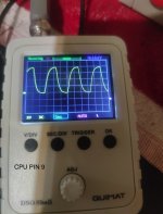
Using the scope, look at all the buffered address lines from BA0 to BA15 one at a time. Start with BA0, it should be a 250 KHz square wave. BA1 will be half that frequency and so on. This is because the CPU is incrementing through all the address space. You will be looking for something that is NOT a perfect square wave: that would be the problem signal. Probe the ROM that is farthest from the CPU or the expansion connector.
-dave_m
Desperado
Veteran Member
- Joined
- Nov 25, 2017
- Messages
- 6,827
Hi Dave_m! we're all Dave hereA first test with the NOP Generator:
Using the scope, look at all the buffered address lines from BA0 to BA15 one at a time. Start with BA0, it should be a 250 KHz square wave. BA1 will be half that frequency and so on. This is because the CPU is incrementing through all the address space. You will be looking for something that is NOT a perfect square wave: that would be the problem signal. Probe the ROM that is farthest from the CPU or the expansion connector.
-dave_m
Must i look BA0 to BA15 directly on the cpu pins?
Thanks!