• Please review our updated Terms and Rules here

Cheapo IDE interface for Model 4p running MM CP/M

ACT32 added and appears to be working fine. CP/M formatted and verified the CF card. Pearce: I guess you can finalize and have boards made.

As far as working in LDOS the driver is being worked on.

Oh how much do you estimate a board will cost? Most likely I will take one.

Some pics of the prototype. 
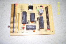
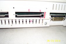
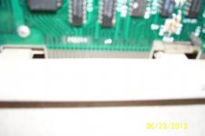
Notice that the even numbered pins on the 50 pin connector are towards the inside. Because of the way my TRS-80 cable was made this is the way I had to do it. Well it was easier for me to do it this way. also the bottom could looked neater but with additions of wires etc. it's just the way it turned out. But it does work so not to big of a deal.

and the prototype in action using CP/M Pics
 

Attachments

  • 100_1153.jpg
    100_1153.jpg
    92.4 KB · Views: 1
  • 100_1156.jpg
    100_1156.jpg
    106.8 KB · Views: 1
  • 100_1157.jpg
    100_1157.jpg
    121.7 KB · Views: 1
  • 100_1159.jpg
    100_1159.jpg
    96.4 KB · Views: 1
  • 100_1160.jpg
    100_1160.jpg
    102.8 KB · Views: 1
Last edited:
Way to go, Frank!! You've even got it laid out on a RadioShack protoboard. Impressive!

I'll certainly be interested in a couple of these boards when available. My Mod 4 has been sitting in the garage for a few years. This will be a good excuse to bring it in and fire it up.
 
Getting a little further with the LDOS drivers. There is some kind of Directory size issue I need to sort out but formatting is definitely working. Its the initialization part that is messing up.

ldos1.jpg
 
Pearce: As I said it may be just my cable. But compared to the one TRS-IAN is using it looks identical see pic in my next post. I used an old SCSI cable and added a 50 pin card edge connector to it. So I would leave it alone. Mainly because my IDC connector end is upside down when connected! See pic in my next post as well and you will see the connector is definitely upside down. But this is how it works for me on this prototype

But this is what I have found out. The even number pins are facing the out side of the bus connector and the odd pin are towards the inside of the connector. Worst case scenario would be just to flip the 50 pin connector around 180 degrees.

To simplify things here is a picture showing the Even pins RED "E" and the odd pins RED "O" Also a red line to indicate pin 1 end. So hopefully no confusion.
 

Attachments

  • 100_1169.jpg
    100_1169.jpg
    79.4 KB · Views: 1
Last edited:
How are you connecting this to a TRS-80 Model 4? I must have missed something, but I can't find in the thread how the board connects to the TRS-80. You mention a 50 pin card edge connector, but i thought these only had an RS-232 and a parallel port.
 
Hey Chuck, nope they have a Floppy port 34 pins RS-232 25 pins Printer port also 34 pins and the expansion port which is 50 pins. This is the Cable TRS-IAN sells with the FreHD HD emulator (PIC). The 50 pin IDC hooks up to the Cheapo IDE or the FreHD. I have attached a couple of picture to explain. The 2 picture is with the Cheapo hooked up to the expansion port. The 3rd Picture shows the port connectors. From the top down is: 34 pin floppy port 25 pin RS-232 facing outward because mine is a Gate Array model IV. 50 pin Expansion for the cheapo or the FreHD or a real TRS-80 hard drive and last is the 34 pin printer port.

So hopefully this clears it up some.
 

Attachments

  • image008.jpg
    image008.jpg
    13 KB · Views: 1
  • 100_1170.jpg
    100_1170.jpg
    90.4 KB · Views: 1
  • 100_1171.jpg
    100_1171.jpg
    91.6 KB · Views: 1
Last edited:
Here are the pictures for the model 4P I have.

For orientation Pin 1 is on the right in both pictures. The ground lines are on the bottom of the connector and the signal lines are on the top. That puts even on the bottom and odd on the top.

Matt

cardedge2.jpgCardedge1.jpgcardedge3.jpg
 
Yes I can actually see the number 50 in the 1st pic. The info about the Modem is that at the bottom portion of the 4P? And the FCC warning about interference is at the top? If so it means even is on top! Pin 50 is a dead giveaway. It is on the even side 2-50 and would put pin 1 on the right side same as mine. If you are doubtful take an Ohm meter check touch pin 50 on the left end and then touch any pin on that row. Should show a short. That's how I did it with mine.
 
Last edited:
Are you sure? :)

I can also see 1 and 49 in my photo. Plus the shot from the bottom clearly shows all the even numbered ground lines tied together. On the top of the connector the lands appear to be going straight to the even number pins but they actually jog around under the silkscreen. If you look real close you can see the lines along side the even numbered feed-thrus.

Maybe I am agreeing with you.

Matt
 
Last edited:
I actually took out my motherboard and looked at it carefully. Yes there are Vias near the even pins but do not hook up to those pins. They are coming from the odd number side of the board. Plus on the odd side there is no trace or via at pin 45. Look at the schematic and nothing is hooked up to pin 45. Like I said ohm it out to be sure. It's the way mine is and Radio shack is to cheap to reverse pins around on a board! I attached a blurry pic but if look carefully this is the even numbered side. You see the traces and they all run into a common ground. Just above you see the vias these are from the odd side.
 

Attachments

  • 100_1165.jpg
    100_1165.jpg
    82.6 KB · Views: 1
Ohm meter shots of the top and bottom of the board. Top, not shorted, odd. Bot, shorted. even. Pin 1 on right in first photo. 2nd photo is sort of upside down.

What am I missing?

Matt

meter1.jpgmeter2.jpg
 
Well darn that makes no sense. Shows number 50 along the top row. But yet they are odd numbers? Well I guess that's the way the 4p is. Ok for orientation purposes. The 1st picture is the top or bottom? The panel flips up. Now do you call the top or bottom?

Ok the row that says 50 ohm from there to any point on that line. What do you get?
 
Last edited:
It seems fairly clear that the connector orientation is likely to cause issues. As the design stands, if the connector is hooked up backwards such that the ground pins are presented to the 'signal side' of the connector, the expansion card will attempt to drive *EXTIOSEL high with that output shorted to ground.

To ensure the board can withstand this without more logic, we could modify the 50-pin header to be N/C at pins 8 and 44 so that U3 would be driving nothing.

Any other suggestions?
 
Ha, me neither :) But I think it should be OK; the purpose of the even grounds is presumably to reduce crosstalk and it would still do that, by virtue of the connection to ground at the host end.
 
I think the design with pins 8 & 44 isolated from ground would be good and I say get the boards made. But only my opinion. What is the average turn around time to have the board made?
 
Fine with me. 3-4 weeks back to whoever orders them. I'm happy to do so and make them available for purchase online, but it will mean another week or two getting from the UK onwards to wherever.
 
Back
Top