daver2
10k Member
Yes...
Dave
Dave
it is a pulse??What is wrong with UD8 pin 20? It is a low going pulse!
Dave
Yes, same chars and same signals!Set the ROMulator RAM link to OFF/OUT and see what the first two characters on the top left of the screen are.
Double check that you have the same measurements again to demonstrate the code is actually working...
Depending upon what we observe, we can then probe the RAM signals with the oscilloscope.
Dave
Now that really is interesting...Yes, same chars and same signals!
Clip it onto the pin...how can i connect oscilloscope ch2 probe on ud8 pin 20 in stable way?
now i have original ram bank configuration!Question. Are your RAM banks 'correct' or swapped over at the moment?
Dave
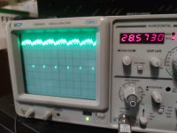
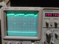
i see only one pulse in the middleThat's OK.
What happens if you speed up the timebase by one click of the knob?
Dave