daver2
10k Member
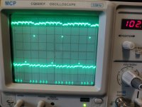
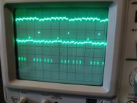
So, I am expecting to see this trace ALWAYS like this on the screen. You appear to have set the oscilloscope up correctly.
If you look back at post #1,096 we get nothing like that do we?
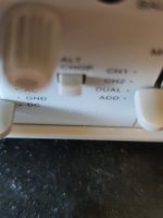
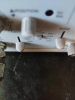
Can you double check that the ALT/CHOP button is pressed IN.
You may need to adjust the oscilloscope trigger level to get the desired result.
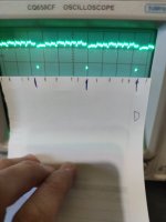
What does your piece of paper look like, because you can't have git the four /CAS0 pulses between the pairs of UD8 pin 20 pulses...
Dave
If you look back at post #1,096 we get nothing like that do we?
Can you double check that the ALT/CHOP button is pressed IN.
You may need to adjust the oscilloscope trigger level to get the desired result.
What does your piece of paper look like, because you can't have git the four /CAS0 pulses between the pairs of UD8 pin 20 pulses...
Dave