• Please review our updated Terms and Rules here

Commodore Pet 3032 no power

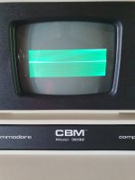
Shaking. I was referring to the brightness change.

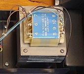
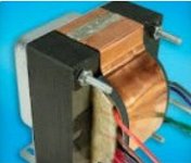
Is it possibly an interaction between the transformer and the monitor?

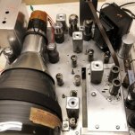
Can you open up the case - and prop it up - and see if the problem either goes away or reduces.

Dave
 
Since it's a non-crtc system, the scan frequency doesn't match the mains, so you can get interference from the transformer making it wobble - or a little ripple after the 18V regulator on the monitor board doing much the same...

As Dave said, if it reduces with the lid up, it's the transformer - some PETs were supplied with a piece of thin metal magnetic screening (what would hopefully have been mu-metal - soft iron) fitted in the top of the lower case, above the transformer to stop this...

It's worth checking the 18V supply carefully and look for a little ripple after the regulator - it sometimes varies as it warms up.
 
Hi Articat and welcome in this precious forum!
Daver2 and many other members they have helped me many times to repair some Cbm PET!
I have always entered here in desperation and now I am only rarely! eheh
 
Since it's a non-crtc system, the scan frequency doesn't match the mains, so you can get interference from the transformer making it wobble - or a little ripple after the 18V regulator on the monitor board doing much the same...

As Dave said, if it reduces with the lid up, it's the transformer - some PETs were supplied with a piece of thin metal magnetic screening (what would hopefully have been mu-metal - soft iron) fitted in the top of the lower case, above the transformer to stop this...

It's worth checking the 18V supply carefully and look for a little ripple after the regulator - it sometimes varies as it warms up.


Yes that is right.

If you have a 50Hz scan rate PET running on 60Hz line power or a 60Hz scan rate PET running on 50Hz line power , there is always the possibility of "interference."

However, this interference does not take the form of ripple on the power supply voltages (unless it is severe and ripple voltage breaks through to the outputs of the voltage regulator IC's, which doesn't happen if the electrolytic caps are ok ).

It takes the form of direct Electromagnetic Radiation, from the iron core of the PET's power transformer, to the CRT beam, in the VDU's cathode ray tube.

If you want to find out if that is happening, or not, you need to unbolt the VDU assembly from the PET computer and move it a foot or two away, to see if the CRT's beam is being modulated from the magnetic field of the PET's power transformer, or not, probably likely not.
Hi Hugo - I did say "OR a little ripple" - and since the pet is non-CRTC, it will not be 50Hz in any case
 
Hi Hugo - I did say "OR a little ripple" - and since the pet is non-CRTC, it will not be 50Hz in any case
I was just giving a "generic example" of the way it might work, when the vertical frame rate doesn't match the line power frequency.
 
You need to see if you can locate some mu-metal to put between the transformer and the monitor.

Let me do a bit of googling - but so can you...

I found a load of references. Most of them commercial. If you ask nicely one of them may send you a free sample or an offcut. It is possible that the usual auction sites purport to have some as well.

You may find some mu-metal shielding in old oscilloscopes etc. If you can find some dead ones anywhere for scrap value, you could strip the mu-metal out and fabricate your own.

You could also try some "Heath Robinson" construction... Open a metal can up and try that!

Dave
 
Last edited:
@daver2
I have some protective shields from C64 and Commodore Amiga. Do you think these shields are made of MU-metal?

I will try these . I'll be back with some new photos when the machine is perfect. :)
 
You may not need a mu-metal shield, it might depend on whether or not your power transformer already has a copper flux band on it, or not ? If it does not have that, adding one, which is fairly simple can do it. Can you take a photo of your power transformer ?
 
Here's a crop from an image attached to post #9.

Worth experimenting with the routing of the PSU and monitor interconnect cables I would have thought.

Alan
 

Attachments

  • 3032 Transformer.jpg
    3032 Transformer.jpg
    727.8 KB · Views: 10
I have attached a photo of a typical flux band on a line power transformer.

They are wrapped around the outside and well soldered together at the overlapping ends. The stray magnetic fields induce a current in the copper and that current produces a magnetic field which opposes the radiated magnetic field. So it works on the principle of Lenz's Law.

One thing about flux bands though, they are pretty hopeless with just thin copper foil, you see a lot of this sort of thing these days because its easy to apply and cheap. In my experience they don't work well "thin" because in this case the induced voltages are low and it requires a low resistance conductor to establish a reasonable reactive current. I think they are best when the copper is at least 1mm thick, perhaps no thinner than 0.4 to 0.5mm thick, but it is harder to cut bend and fold and solder 1mm thick copper to make an effective band.

Other tricks that can minimize the radiation from the transformer, put the transformer up on some fiber washers to reduce the magnetic coupling to the metal case and try rotating/manipulating the transformer position. Designers of vintage TV's struggled with this problem too, if you look at the attached chassis photo of a vintage TV from 1948, you with see three things:

Power transformer at an odd angle on the chassis corner.
Flux band on transformer (it is copper just Painted Black as Mick Jagger preferred it).
Mu-Metal shield on the CRT too.

There is another thing you can check. As the line power voltage increases, the radiated flux from the transformer increases in a non linear way and even small increases can push it up due to the primary magetization current increasing due to core saturation on peaks. So check your line voltage just in case it is running high. All else equal, this problem is aggravated on 50 Hz line supply too compared to 60Hz. Try reducing the line supply voltage on a Variac by 15% and see if that has any practical effect on the interference.
 

Attachments

  • fluxband.jpg
    fluxband.jpg
    46.5 KB · Views: 5
  • fluxband2.jpg
    fluxband2.jpg
    111.6 KB · Views: 5
Last edited:
Hello again guys!
My Pet has been running a while now! But yesturday something happend with my screen!
The cursor is still blinking but the screen is garbage. This happen after 15min of use. Look at the picture...
Is this a screen problem? I havent recap the screen yet.
 

Attachments

  • 20230722_173944.jpg
    20230722_173944.jpg
    2 MB · Views: 4
Yes, that is an example of partial vertical scan collapse.

It is most likely the monitor (it could, for example, be the vertical height potentiometer) but it could also be something else or the main logic board.

You will need to check the VDRIVE and HDRIVE signals between the PET logic board and the monitor (with an oscilloscope) to identify the culprit.

Remind me, do you have an oscilloscope?

Dave
 
Yeah I have a ocilloscope. One digital and one analog. So where do I find these signals?
 
J7 pin 3 for the vertical drive (on the connector on the PET logic board).

The key (missing pin) is on J7 pin 6 - so you should be able to work out which is pin 3 from that.

Actually, that should be enough. It should be a 50Hz (or 60Hz) 5V TTL signal.

Dave
 
Back
Top