• Please review our updated Terms and Rules here

Commodore PET 8032-B monitor issue

I have a cheaper multimeter here which doesn't have an ohmmeter but does have continuity on it; From what I gather you put the positive cable on the middle pin and the negative cable on either of the other pins?

never mind.. it's printed on the board
 
Ok just to clarify what I'v done here...
There's E C and B marked on the board, I place the red cable onto the base.. then the black cable on to the collector... This has given me a very weak reading on the multimeter (closed circuit being 0 and open being 1) initially 200 then would go above 1000 - this was the same story for all of the transistors (I assume the large one with the heatsink is part of that circuit? I couldn't find the fourth one..) except for the first one, which wouldn't respond at all.. I tried all the them 3 or 4 times.. all of the respond except for the first one
 
int,
I'm not sure of your meter. Does it have a 1 K ohm scale or does it just buzz with a short? Normally you select the 1K range of an ohmmeter (do not use auto-range) and the leads will have a voltage of about 1.5 V across them in anticipation of measuring resistance. When you place them across the base to emitter junction of the transistor, if it foreword biases the junction you will get a low resistance reading. When you reverse the leads, you should reverse bias the junction and you will get a high resistance reading. If this happens you know that junction is working. Then you try the same process on the base to collector junction.

In older VOMs if you chose a higher scale like > 10K ohm, the meter used a +9V source and it might damage the transistor.

In your case I'm not sure how your multimeter operates in 'continuity mode'.
 
It's an odd one.. it's a cheap multimeter so how it works I am not exactly sure.. 0 for a closed circuit (i.e touching probes off each other) and 1 for open.

I brought my proper multimeter home with me tonight.. according to the Zimmer schematic all of the transistors along the top where the "Video In" line is are NPN (these are the ones I am supposed to be testing, right?).. however the very first transistor in my board is looking like a PNP transistor.. hence why I thought it wasn't working the first time round
It is also different in physical shape...
All the other transistors are working on the ohmmeter (i.e a closed circuit with little resistance in a 2k scale (0.830,0.770,1.2 respectively for the latter 3 transistors)
They do not respond when I reverse the probes


http://zimmers.net/anonftp/pub/cbm/schematics/computers/pet/8032/321448.gif
 
Sorry for jumping in here. I haven't read all the post (there are a lot), but the dead monitor symptoms sound very similar to the problem I was having with my PET 64:

http://www.neoncluster.com/projects-pet/pet-64repair.html

The issue turned out to be a dead resistor on the video board...I believe the resistor was meant to act like fuses and blow if too high voltages were present.
however I can't remember if the monitor in the PET 64 is the same as the 8032 or not.

Phil
 
Again, not sure if this is the same problem or even the same monitor used in the 8032, but here are some images showing the two resistors I replaced in the PET64 video board. Not sure if both were dead, but one certainly was, and the other I replaced for good measure as it was reading a little funky.

PET64 screen fix 2.jpg

PET64 screen fix 1.jpg

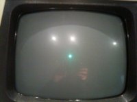
One thing that makes me think it could be a similar issue is that you say you sometimes got a glowing dot in the center of the screen that wiggled, this sounds very similar to what I was getting before the fix.

PET 64 dot.jpg

Actually I'm surprised I still have all these photos that I shot during the fix.

Phil
 
Actually I'm surprised I still have all these photos that I shot during the fix.

Phil,
I think it is good that you kept a photo record of your repairs in case other PET guys can benefit. I remember your repair so long ago of an offset text issue in your display. What a long trail that was! I remember those detailed scope photos you took that found the culprit chip in the end.

As you know Tezza also keeps good records of his fixes on his many ancient machines and publishes them on his blog.
-Dave
 
Hi guys
Sorry for the delays.. I'm opening a shop in town so have been really busy..
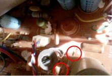
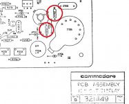
Anyway thanks Nama & Dave! I tested R752 and R753 which are by the large circular thingy in the right hand bottom corner. I set the multimeter to the scale of 2M... R752 came up around 1470... however no response at all for R753... nothing. Open circuit as far as the DMM was concerned.. So it's either out of that scale or broken? I will test the transistors now.. I did the wrong ones originally...

http://zimmers.net/anonftp/pub/cbm/schematics/computers/pet/8032/321449.gif
 
So your meter does have an ohms scale after all? On the 2M range you'd probably read 0 ohms; on a more reasonable 200 ohm scale they should both read around 56. Surprising that you'd still have high voltage if those two resistors are really bad...

You are measuring across these resistors, and not to ground or elsewhere by any chance?

Instead of using words like "round circular thingy" why not make things a little easier for us and refer to their labels or the Parts Arrangement Diagram and call them what they really are (e.g. T721, C754 or Width/L723).
 
Last edited:
I bought home my proper meter; the original one I had doesn't.. I get no reading from any of the resistors around there on 200 range... Something weird going on here.. (I'm not doing it wrong in case you're thinking that :p Set to 200ohms.. probe on either end of the resistors metal!)
 
I bought home my proper meter; the original one I had doesn't.. I get no reading from any of the resistors around there on 200 range... Something weird going on here.. (I'm not doing it wrong in case you're thinking that :p Set to 200ohms.. probe on either end of the resistors metal!)
Is the meter working? 0 ohms if you touch the probes together?
 
R752 seems a bit temperamental too, upon contact the values on the screen will change before it settles at open circuit/1
And yes I am measuring across the resistor, not to a ground/earth.
 
It looks like we are hot on the trail and may have the problem. Be super careful around the high voltage transformer T721. Power must be off with the resistance measurements and it may be good to discharge the CRT. Mike can tell us how.
-Dave
 
R752 seems a bit temperamental too, upon contact the values on the screen will change before it settles at open circuit/1
And yes I am measuring across the resistor, not to a ground/earth.
Couldn't hurt to replace them I suppose.

Have you removed the board, i.e. can you measure on the bottom of the pcb? Do the other resistors measure more or less what they should?
 
Couldn't hurt to replace them I suppose.

Have you removed the board, i.e. can you measure on the bottom of the pcb? Do the other resistors measure more or less what they should?
Yeah I am measuring from underneath the PCB to ensure contact.

I tested these two resistors:
R262 = 56kOhms
R260 = 0.582 megaOhms
R201 = 2.2kOhms
 
Last edited:
Back
Top