DistantStar001
Experienced Member
- Joined
- May 8, 2019
- Messages
- 178
So I've been on a bit of a repair kick lately, and am now turning my attention to one of my more stubborn machines. It's a later Commodore PET, model CBM 8032. When I got it, its power cord had been chewed through near the base of the machine, and the stem on the CRT had been broken off, just behind the connector to the neck.
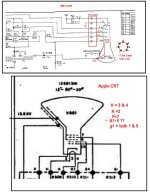
Since then, I've shortened the cord past the area where it had been chewed. And have been able to determine that the computer is working. It gives a boot chime, and an error chime if I max out the characters in BASIC. The old CRT had the analog board spitting sparks, so I've tried to replace it with one salvaged from an old Apple Monitor II that had some broken inside plastics. Nonetheless, the CRT does work, as I tested it with an Apple II prior to salvage. Unfortunately, I'm still not getting a picture. I've tried adjusting the controls on the analog board and got nothing. However, I am getting high voltage! and the heater is warming up. I checked the pins on the motherboard with an oscilloscope, and I am getting both vertical and horizontal sync signals. The screen also physically fits into the case, and the neck connector fits as well.
At this point, I'm guessing that the pinouts between the screen I had and the replacement are different in some way, but I haven't been able to locate a schematic of either the CRTs or the boards to confirm this.
The monitor I had was an Amperex M31-334GH. The replacement I have is a Samsung 12GBY31N. My question here is: Can I adapt the Samsung to work with my PET?
Also, could there be another culprit keeping me from getting a picture?