• Please review our updated Terms and Rules here

Commodore PET 8032 Monitor problem(s)?

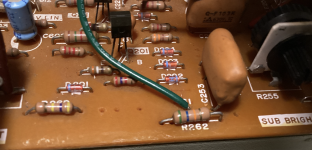
I've got the same analog board in my pet I believe... Issues I've had with it where dirty brightness pot and cracked solder joints on the main connector (upper right in your picture)
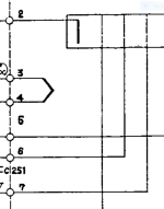
This should be the correct schematic http://www.zimmers.net/anonftp/pub/cbm/schematics/computers/pet/8032/321448.gif
Thanks for this! I've checked the solder joints and didn't see anything. But I'll go over it again to be sure.

Even though the first schematic wasn't the right one for my board, it does appear that the wire color codes given are the same.

Remeasuring with my multimeter, this is what I got:

Green G1: Brightness turned all the way to the left, -141.7v; all the way to the right, -81.7v (sub brightness makes no difference)
Red G2: -329v
Blue G4: Focus (wasn't expecting that) turned all the way to the left, 48.6v; all the way to the right, 275v (sub brightness makes no difference)
 
Thanks for this! I've checked the solder joints and didn't see anything. But I'll go over it again to be sure.
It wasn't visible in my case (without a microscope), I reflowed it based on experiences other forum members had.

I cannot say much about the specific voltages and you may wait for the others to continue the troubleshooting process, but while you wait if you've got the time: my approach would be to check if you get the correct drive and video signals and follow them from there (left to right on the schematic, compare the circled numbers on the schematic with the waveforms here http://www.zimmers.net/anonftp/pub/cbm/schematics/computers/pet/8032/, 321450-*.gif)
 
Your board is the later version, that is easily recognized by the presence of the width control inductor, the magnetic linearity coil L724 (which is dipped in orange resin and has a permanent magnet in it, check that with a screwdriver blade to feel the magnetic force) and the power resistors that shunts some current across the regulator IC to lower the thermal dissipation in the regulator.

In the earlier 9" VDU model, these parts were not present and the horizontal scan linearity was sub-optimal and the 7812 regulator had a larger heat sink, which was borderline to keep it out of thermal shutdown.

They moved to the 7818 regulator for the 12" VDU, this gave more scan width, which then allowed the use of the width and linearity inductors. They did a similar thing with the later 9" VDU's.

It is a simple VDU and easy to fix if you can make accurate recordings of the CRT's cathode, grid and first anode voltage. And we can then figure out why the CRT is not lighting up.
 
Last edited:
From left to right in the gun diagram above, it is Cathode, g1 grid, A1 anode and then focus electrode. Not shown in the diagram above is the final anode (EHT) which is a pair of electrodes on either side of the focus electrode. Inside the CRT these two are connected to the internal conductive coating of the bulb, and the anode clip on the side wall of the CRT. As Daver2 mentioned there is no need to go anywhere near that EHT connection, it is safe under its insulated cap and there is no need to discharge the bulb either, that is if you don't go under that insulated cap.

It is generally the relative cathode to g1 voltage that controls the beam current (brightness) when that is zero, the beam current is at max. It generally takes around 40 to 50V (grid negative with respect to the cathode) to extinguish the beam. The A1 anode voltage needs to be at least a few hundred volts positive, with respect to the cathode, to accelerate the electrons toward the screen and the EHT does the rest.
 
>>> Sorry, probably should have posted this sooner.

A picture paints a thousand words...

All of the DC voltages below are all relative to GROUND/0V.

The cathode (k) electrode (pin 2) should vary between 0V and +30V.

The grid (g1) electrode (pins 1 and 5) should vary between 0V and -155V (dependent upon the main brightness control R261).

The anode (A1) electrode (pin 6) should vary between 0V and +400V (dependent upon the sub-brightness control R255).

The focus electrode (pin 7) should vary between 0V and +400V (dependent upon the focus control R253).

Please DO NOT adjust ANYTHING until you have taken the measurements though.

From the measurements, we can suggest the best location to look for the fault.

As has been already mentioned, there are a number of failure modes that can occur: the potentiometer wipers may not be making good contact. Any series resistors may be defective. The associated power supply may be faulty. We won't know which of these fault scenarios is/are present until we take the measurements...

Dave
 
K (Yellow) (Pin 2): +28.5
G1 (Green) (Pin 1, 5 no connection): -112.5
A1 (G2) (Red) (Pin 6): +121.3v
G4 (Blue) (Pin 7): +127.9v

All measurements taken from the neck connector. Nothing adjusted. Not sure why I had a negative reading on pin 6 before (probably the power of suggestion), but I remeasuered several times now and the reading is definintly positive. Everything seems to be within their appropriate range.
 
With such a high negative grid voltage of about -141 volts, with respect to the cathode, all the emitted electrons from the cathode are repelled back to it. So there will be no beam current and the CRT face will be black.

Check the circuit that controls the -115v, is the brightness control defective or simply turned fully one way ? Is R260 in the leg of the brightness control to the ground open circuit ?

(the A1 and G4 voltages will measure a little lower than they actually are because of the current drawn by the meter, because they are high resistance circuits)
 
Last edited:
It wasn't visible in my case (without a microscope), I reflowed it based on experiences other forum members had.
Reflowed and added fresh solder. Sadly, didn't help.

Check the circuit that controls the -115v, is the brightness control defective or simply turned fully one way ? Is R260 in the leg of the brightness control to the ground open circuit ?
From what I can tell, adjusting the brightness alters voltage on G1 (Green) and the knob is turned about half way. R260 is connected to the right leg of the brightness adjustment (with the knob facing to the back of the machine) and connects to ground on the other side. If I'm reading the color code right (the bar between the two yellows is a bit faded so I can't tell if it's violet or blue), then it's either a 460K or 470k resister.
 
Note the position of the control (if possible).

Turn the control fully one way and measure the voltage on the CRT base.

Turn the control fully the other way and measure the voltage on the CRT base.

Return the control to where it was originally and check that the voltage on the CRT base has returned to its approximate reading as measured previously.

Dave
 
Pin 1: GREEN: left -81.8v right -142.4 start-112.1 return -112.6
Pin 6: RED: left +325 left +100.9 start 123.1 return +121.0
Pin 7: BLUE: left +274 left +42.7 start +86.6 return +87.5

I may not have gotten them back to their exact positions, but they're as close as I could.
 
The negative voltage on the grid is still far too high, have you checked the resistor R260 ?

But having said that, there is something odd with the schematic. If the brightness potentiometer really is 250k and the series resistor 470 k, then the lowest (least negative grid voltage) one could get would be about -100V , but this is far, far, too negative to get any CRT beam current. Can you disconnect R260, measure its value on a meter and measure the brightness potentiometer value on the meter and take a close up photo of R260.
 
Last edited:
R260 certainly looks like a 470k on the previous board photo. The only way this could make any sense is if the brightness pot was 2.5 Meg, not 250k, this would get the min negative grid voltage down to about -25V.

One other thing, check the value of R262, the 56k in series with the grid, in case it has gone O/C.

The only other thing I can think of is that the original CRT gun required a very high unusual negative grid voltage to extinguish the beam. If this is the case, then to gain brightness control over a more standard CRT, short out the 470k resistor.
 
Last edited:
R260 Verified as a working 470k (removed). R262 also verified as 56k (removed), in sequence gives an 0.055 on the 2 MOhm range. Both resisters have been reinstalled.

Screenshot 2023-05-21 at 9.44.30 PM.png

Almost forgot the picture. R260 is included to the left. Also the Brightnes control gives between 0 and 350k (dances around that reading but never realy settles).
 
Last edited:
Tack a 47k resistor across the 470k, or install a 47k instead, that will lower the range of negative grid voltages provided by the brightness control and see if adjusting the brightness control allows anything to be seen on the CRT face.
 
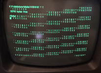
Kinda SUCCESS!!!!

Screenshot 2023-05-21 at 11.13.35 PM.png

New question: What's causing the garbage on the screen? Honestly, it may have been there all along... But you know, I couldn't see it.
 
Well the new CRT was working the whole time, you just couldn't see it because the beam was extinguished by the high negative grid voltage. It looks like your computer needs some work now.
 
Well the new CRT was working the whole time, you just couldn't see it because the beam was extinguished by the high negative grid voltage. It looks like your computer needs some work now.
Very true. But thanks to you and dever2 At least I can see what I'm doing now!
 
Vision is a wonderful thing...

Looks like something now in the ODD video RAM circuit is causing a problem (to start with of course).

See the schematic here: http://www.zimmers.net/anonftp/pub/cbm/schematics/computers/pet/8032/8032029-09.gif.

Check for activity on: UB8 pins 1 and 11 and see what the signals are like on all of the pins around UB8.

It could be one of UC6 or UC7 (the video RAMs themselves). This is the most likely cause.

I did a very quick Ohm's Law calculation for the series-connected R260 and R261 and got a minimum voltage of -98V and a maximum voltage of -150V (this is the swing from one end of R261 to the other). This calculation ignores the presence of R262 in series with the grid. These voltages are in line with the readings you took previously.

Dave
 
Last edited:
Back
Top