Upcoming Events:
- VCF South West - June 14 - 16, Davidson-Gundy Alumni Center at University of Texas at Dallas
- VCF West - Aug 2 - 3, Computer History Museum, Mountain View, CA
- VCF Midwest - Sept 7 - 8 2024, Schaumburg, IL
- VCF SoCal - Mid February 2025, Location TBD, Southern CA
- VCF East - April 2025, Infoage Museum, Wall NJ
-
Please review our updated Terms and Rules here
You are using an out of date browser. It may not display this or other websites correctly.
You should upgrade or use an alternative browser.
You should upgrade or use an alternative browser.
Commodore Pet 8032SK with monitor not working
- Thread starter Desperado
- Start date
daver2
10k Member
I'll start us off then...
Board layout: http://www.zimmers.net/anonftp/pub/cbm/schematics/computers/pet/8032/321449.gif
Schematic: http://www.zimmers.net/anonftp/pub/cbm/schematics/computers/pet/8032/321448.gif
If you use your multimeter (to read 20 V dc full scale) to measure the voltage on both ends of inductor L721 (with reference to GND/0V) you should find approximately 18 V dc on both sides of inductor L721. If it was me, I would solder a black wire onto a convenient GND/0V point and use that as one side of my measurements, and two wires (one on each side of inductor L721) to remotely read the voltage. That keeps your fingers (and more importantly your heart) well away from the high voltage innards!
I have just found TP1 on the PCB layout - that should be 18 Volts dc (and is probably easier to get than L721).
You will notice on the schematic numbered points. These relate to oscilloscope readings that you will find in the directory http://www.zimmers.net/anonftp/pub/cbm/schematics/computers/pet/8032/.
Do ***NOT*** attempt to read any voltages above 35 Volts (or so) with your little oscilloscope.
You should be able to view the video, horizontal and vertical signals as they enter the monitor PCB from the main board on your oscilloscope and they should look like the identified waveforms numbered as (1), (13) and (3) respectively.
You should be able to follow the video signal (1) and (2). Note that (2) is approximately a 30 Volt signal - so 5 Volts/division is required on the oscilloscope.
You should also be able to follow the vertical drive signal all they way through on the oscilloscope. The highest voltage looks to be in the range 18V to 20V.
The horizontal drive circuitry requires much more care - as this is where there are high voltages. Let's look at that one last...
Dave
daver2
10k Member
No problem. I was sat here working on my Parallax Propeller project for work anyhow...
Dave
Dave
Desperado
Veteran Member
- Joined
- Nov 25, 2017
- Messages
- 6,827
I'll start us off then...
Board layout: http://www.zimmers.net/anonftp/pub/cbm/schematics/computers/pet/8032/321449.gif
Schematic: http://www.zimmers.net/anonftp/pub/cbm/schematics/computers/pet/8032/321448.gif
If you use your multimeter (to read 20 V dc full scale) to measure the voltage on both ends of inductor L721 (with reference to GND/0V) you should find approximately 18 V dc on both sides of inductor L721. If it was me, I would solder a black wire onto a convenient GND/0V point and use that as one side of my measurements, and two wires (one on each side of inductor L721) to remotely read the voltage. That keeps your fingers (and more importantly your heart) well away from the high voltage innards!
I have just found TP1 on the PCB layout - that should be 18 Volts dc (and is probably easier to get than L721).
You will notice on the schematic numbered points. These relate to oscilloscope readings that you will find in the directory http://www.zimmers.net/anonftp/pub/cbm/schematics/computers/pet/8032/.
Do ***NOT*** attempt to read any voltages above 35 Volts (or so) with your little oscilloscope.
You should be able to view the video, horizontal and vertical signals as they enter the monitor PCB from the main board on your oscilloscope and they should look like the identified waveforms numbered as (1), (13) and (3) respectively.
You should be able to follow the video signal (1) and (2). Note that (2) is approximately a 30 Volt signal - so 5 Volts/division is required on the oscilloscope.
You should also be able to follow the vertical drive signal all they way through on the oscilloscope. The highest voltage looks to be in the range 18V to 20V.
The horizontal drive circuitry requires much more care - as this is where there are high voltages. Let's look at that one last...
Dave
Hi Daver2,
i saw TP1 voltage on pcb and i read 23,2 V...
where i can see video signal with scope??
Thanks
daver2
10k Member
23.2 Volts is too high. It should be 18.0 Volts. Is the regulator (IC901) short circuit?
Can you measure the voltage on all three terminals of IC901 please. One pin will be the input voltage; one pin will be ground and the third pin should be the output voltage. We can work out which ones they are when you have measured them...
To measure the video signal, look on the schematic I referenced for the video signal. This is associated with the number (1) which is connected to the 'bar' of D201. That is where to measure the signal.
Dave
Desperado
Veteran Member
- Joined
- Nov 25, 2017
- Messages
- 6,827
23.2 Volts is too high. It should be 18.0 Volts. Is the regulator (IC901) short circuit?
Can you measure the voltage on all three terminals of IC901 please. One pin will be the input voltage; one pin will be ground and the third pin should be the output voltage. We can work out which ones they are when you have measured them...
To measure the video signal, look on the schematic I referenced for the video signal. This is associated with the number (1) which is connected to the 'bar' of D201. That is where to measure the signal.
Dave
ok,
IC901:
INPUT:32V
OUTPUT:23,6V
daver2
10k Member
It's obviously regulating the voltage (so it isn't short circuit). But it is either still too high, or your multimeter is reading high, or there is a lot of ripple.
Can you measure the DC voltage with your oscilloscope instead? DC coupling, 5Volts/division and 10 ms/division.
See what the oscilloscope indicates for comparison.
Dave
Can you measure the DC voltage with your oscilloscope instead? DC coupling, 5Volts/division and 10 ms/division.
See what the oscilloscope indicates for comparison.
Dave
Desperado
Veteran Member
- Joined
- Nov 25, 2017
- Messages
- 6,827
It's obviously regulating the voltage (so it isn't short circuit). But it is either still too high, or your multimeter is reading high, or there is a lot of ripple.
Can you measure the DC voltage with your oscilloscope instead? DC coupling, 5Volts/division and 10 ms/division.
See what the oscilloscope indicates for comparison.
Dave
Ok, 19,06 V with the scope on test point1.
daver2
10k Member
That sounds better...
I suspect your multimeter is reading high...
You should be able to now look at the video signal at the 'bar' end of diode D201. Set the oscilloscope for 1Volt/division. You will have to speed the timebase up to get to see the video signal detail.
Dave
I suspect your multimeter is reading high...
You should be able to now look at the video signal at the 'bar' end of diode D201. Set the oscilloscope for 1Volt/division. You will have to speed the timebase up to get to see the video signal detail.
Dave
Hugo Holden
Veteran Member
Once the power supply rails are known to be good and assuming the horizontal drive signal is present at point 13 on the schematic, the first thing to check would be if the H output stage is working. If it is working, then 400V will be present on the output (cathode) of D752. A less risky place to test, if your meter was not up to a 400V value, would be the E30 test point.
If the H scan output stage is not working there will be no EHT and the screen will be black.
In these monitors the most vulnerable two transistors are the H output transistor Q721 and the driver transistor Q711. The reason being is that if they are presented with an abnormal drive signal from the computer, then more energy is stored in the line opt transformer, Q721's collector voltage gets exceeded and when it fails it takes out Q711 in the process. It was a risky design relying on the timing of the HOR.DRV signal from the computer.
It is interesting they tacked in an over-voltage detect circuit, but that won't always save Q721. It is also worth checking the energy recovery diode D721 for shorts and the other diodes around the line opt transformer area.
Last edited:
Desperado
Veteran Member
- Joined
- Nov 25, 2017
- Messages
- 6,827
Once the power supply rails are known to be good and assuming the horizontal drive signal is present at point 13 on the schematic, the first thing to check would be if the H output stage is working. If it is working, then 400V will be present on the output (cathode) of D752. A less risky place to test, if your meter was not up to a 400V value, would be the E30 test point.
If the H scan output stage is not working there will be no EHT and the screen will be black.
In these monitors the most vulnerable two transistors are the H output transistor Q721 and the driver transistor Q711. The reason being is that if they are presented with an abnormal drive signal from the computer, then more energy is stored in the line opt transformer, Q721's collector voltage gets exceeded and when it fails it takes out Q711 in the process. It was a risky design relying on the timing of the HOR.DRV signal from the computer.
It is interesting they tacked in an over-voltage detect circuit, but that won't always save Q721. It is also worth checking the energy recovery diode D721 for shorts and the other diodes around the line opt transformer area.
Hi Hugo, at the end of D752 i have 0v....i set my multimeter to 1000V scale
daver2
10k Member
There is no video signal there...
The $64,000 question is "do you have a video signal and the horizontal and vertical drive signals at the monitor connector of the PET main board"? If not, there is no point in going further with the monitor unless the main board is working...
Dave
The $64,000 question is "do you have a video signal and the horizontal and vertical drive signals at the monitor connector of the PET main board"? If not, there is no point in going further with the monitor unless the main board is working...
Dave
Desperado
Veteran Member
- Joined
- Nov 25, 2017
- Messages
- 6,827
There is no video signal there...
The $64,000 question is "do you have a video signal and the horizontal and vertical drive signals at the monitor connector of the PET main board"? If not, there is no point in going further with the monitor unless the main board is working...
Dave
Sure, Pet's board is working 100%
daver2
10k Member
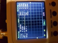
>>> This is video signal at point 9 after d201
Ah, but you didn't do what I asked you to do...
"You will have to speed the timebase up to get to see the video signal detail."
Your photograph of the video signal shows a timebase of 10 milliseconds/division which is far too slow to resolve the video signal.
Dave
Ah, but you didn't do what I asked you to do...
"You will have to speed the timebase up to get to see the video signal detail."
Your photograph of the video signal shows a timebase of 10 milliseconds/division which is far too slow to resolve the video signal.
Dave
Desperado
Veteran Member
- Joined
- Nov 25, 2017
- Messages
- 6,827
>>> This is video signal at point 9 after d201
Ah, but you didn't do what I asked you to do...
"You will have to speed the timebase up to get to see the video signal detail."
Your photograph of the video signal shows a timebase of 10 milliseconds/division which is far too slow to resolve the video signal.
Dave
If i set up timebase i can't see nothing....
The problem is that i don't have 400v
daver2
10k Member
Well, you don't have a video signal either by the look of it. So even if you did have 400 Volts, you would still have a picture of a black cat in a coal cellar at midnight...
Dave
Dave
Hugo Holden
Veteran Member
As noted before, for the monitor's H(horizontal) output stage to be working (and get the 400V and the other outputs from the horizontal output transformer) the HOR.DRIVE signal must be present and normal and of course the power supply must be good and the monitor H circuitry good.
So with no 400V , first check the HOR.DRIVE signal and if that is not there, the problem likely is in the computer, not the monitor. If it is there & normal, then the problem is in the video monitor , likely in the H driver or H output transistor stages.
So with no 400V , first check the HOR.DRIVE signal and if that is not there, the problem likely is in the computer, not the monitor. If it is there & normal, then the problem is in the video monitor , likely in the H driver or H output transistor stages.


