Grizzly Adam
Member
What does the side of the connector look like where the two side grounds connect? What is being called pins 1 & 2 here.


Thanks. I am trying to make as accurate a replica as a can, and I am rebuilding the battery pack so I might hit you up for more info later if you have an actual wall adapter (not the car adapter). But no matter which adapter you have, I am curious about how that interact with those supposed grounds. I almost wonder if they are just for retention and they are only coincidentally grounded (as others have reported, anyway).Oh wow. I never realized those were grounds, actually never realized those existed. I have a PS I can see if there are any contacts on the plug for those.

Can you please do continuity testing on the 18v charge and tell me what pins have continuity? I am wanting to make sure I get the battery charging circuit connected correctly because I will be rebuilding my battery pack as well.I have the AC power adapter, not the Car DC one.
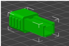
Attached is the plug I had started working on. It wasn't designed for the Adafruit connector as I hadn't made that discovery yet. What it could do was take in 6 stranded wire carefully pushed through the back of the plug, one or two strands a time and extended past the other end, then bunched together carefully and pushed back into the receptacle. It was a very tight fit by design. A little super glue would keep them in place. I didn't like the look or the quality of the wires and they weren't available in super long lengths as I'd like. In a pinch though, it's a good idea at least to get power to the Compaq. I didn't print it for looks yet, this ws more of a fitting. Once satisfied I'd increase the resolution and make it pretty, also need to cap the end where the wires come out to the power supply.
View attachment 1263426
Sure. I broke my leg a couple of weeks ago but luckily the power supply and voltmeter are accessible by crutch.Can you please do continuity testing on the 18v charge and tell me what pins have continuity? I am wanting to make sure I get the battery charging circuit connected correctly because I will be rebuilding my battery pack as well.
I saw on a video that it takes a heat gun and a long time to crack into one.Sure. I broke my leg a couple of weeks ago but luckily the power supply and voltmeter are accessible by crutch.
Also, if you get the battery case cracked open, please share any tips. I've tried multiple times and never even get a light crack. Wondering if the lid is completely glued to the bottom. I have two or three that I would like rebuilt for my 3 SLTs.

Yes I have. I know where the voltages come in, what I am wondering is if there are continuity between any of the pins. Maybe some of them form a bridge to charge the batteries?Measuring the power out from the cable is harder than expected. I can only assume the output voltage depends on what the battery charging sensors are reading for how low the battery state is in as my voltages read much smaller than expected. My guess is that the power output depends on the voltage read in on the battery sensor lines. I get 6.26 volts out of line 4 in the picture when the power supply is not plugged into the computer. I know this power supply is good as it charges an SLT that has a working battery.
Also, the metal around the plug is producing voltage. I measured +2.5 compared to ground. I do feel voltage when I touch it which is probably not good.
View attachment 1264318
Have you read this post?
(1) Compaq SLT/386 or SLT/286 Power Supply Pinout | Vintage Computer Federation Forums (vcfed.org)