MikeS
Veteran Member
Odd, but that explains itYes, it is a DP switch. Not in the conventional 110V monitors (so not in the schematic) but it is in this one.
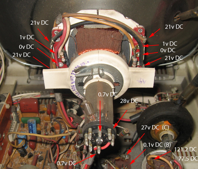
Normally an AC voltage on those filter caps would just be ripple of a few volts riding on top of the high DC voltage; however, if the cap were open and there were no filtering anywhere else then you would get a pulsating DC voltage (i.e. the 'ripple' would effectively be the entire applied voltage). But in no case should it be higher than or even close to the cap's working voltage of 175V.Ok. this might be a clue. I've been measuring in all in AC, thinking this part of the circuit is AC (Duh!). Oh course when I think about it, things like diodes have no place in an AC circuit do they? (or do they?). But then if it's all DC why should there be any AC voltage showing at all?
That's the 'tricky part' I mentioned in the beginning; in the 'low voltage' (relatively speaking) supply from the AC line anything past the diode(s) should be DC. However, the horizontal output stage is effectively actually a second switching mode power supply, shown in the lower section of the power supplies on the left of the schematic ('part of T101'), so you will see high-frequency AC there as well, rectified with a diode where DC is needed.The schematic doesn't specify AC or DC but I guess it assumes you just know. Having learnt a bit a about 5 and 12V DC logic circuits from problem solving and repairs, it looks like I still have a bit to learn about AC/DC conversion circuits. Where in the schematic does the current turn from AC to DC?
Sorry, no promises!I'll do some DC measurements tonight. Promise me I won't fry my multimeter.")
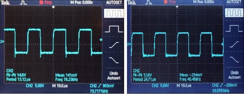
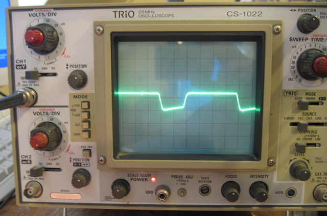
Scopes are generally quite forgiving and an out-of-range trace will just be invisible off the screen, but if you're unsure measure with the meter first; as with the meter, set the voltage range to what you're expecting before you put the probe anywhere, especially in the horizontal output section.Yes, I do have a scope now. I did drag it out and consider using it but, but given I'm a newbie at TV circuits I didn't want to accidently blow it up. If I did zap something I'd rather is be my $30 digital multimeter. However, I'll start using it.
I suspect that the horizontal oscillator is not actually running so you probably won't encounter any of its high voltages (unless you accidentally fix the problem ;-) ) but be careful anyway. When the monitor is working the dangerous voltages are not really the anode of the CRT which is what most people warn about because it is several thousand volts and can still be present after you turn it off, but the several hundred volts at much higher current around the HO transistor & HOT and the socket of the CRT.
Keep one hand in your pocket.
Last edited: