• Please review our updated Terms and Rules here

CPC 6128 BAD KEYBOARD

Desperado

Veteran Member
Joined
Nov 25, 2017
Messages
6,827
Good morning and Happy 2023 from Italy,
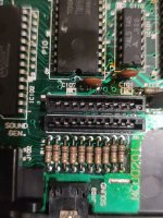
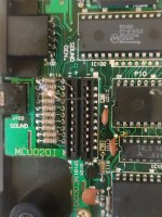
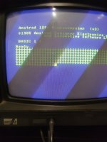
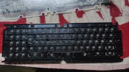
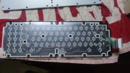
I write this post to ask help, it's a CPC6128, when I turn it on, it writes the characters by itself, some keys write two characters instead of one and some don't work . I have opened and cleaned the membrane and the small springs under the keys, I have cleaned the connectors but the problem remains. If I move the membrane attachments slightly, it no longer writes by itself. What can I do please? Thank you so much!
 

Attachments

  • 1672572236442.jpg
    1.5 MB · Views: 2
  • 1672572236459.jpg
    2.1 MB · Views: 3
  • 1672572236477.jpeg
    1672572236477.jpeg
    2.2 MB · Views: 3
  • 1672572236496.jpeg
    1672572236496.jpeg
    2.3 MB · Views: 3
And a happy new year to you too.

If you check here you will see the key matrix described: https://archive.org/details/Amstrad...Amstrad_Consumer_Electronics/page/n5/mode/1up.

The keyboard is just a simple key matrix.

By disconnecting the keyboard and using a low-value resistor to jumper the row to column on the two keyboard connectors (CP101 and CP102) you can simulate a keypress.

If this works fine, the problem is in the keyboard membrane.

You can purchase replacement keyboard membranes.

Dave
 
Thanks so much Dave, you always know everything! ;)
So, for example if i wanna press "ESC" key, need i use a resistor between pins 5 and 11.... correct?
 

Attachments

  • Screenshot 2023-01-01 alle 13.40.35.png
    Screenshot 2023-01-01 alle 13.40.35.png
    79.5 KB · Views: 2
>>> So, for example if i wanna press "ESC" key, need i use a resistor between pins 5 and 11.... correct?

Correct. But I would choose a number or letter key first 😀...

>>> Thanks so much Dave, you always know everything!

Not everything, but (fortunately) most computers are very similar - both in design and diagnosing faults 😀...

Dave
 
I have only these two connectors on board but they don t match respect diagram...
 

Attachments

  • 1672581971488..jpg
    1672581971488..jpg
    1.7 MB · Views: 3
If you check on PDF page 16 of the document I linked to you will find the two (2) 10-pin connectors (CP101 and CP102) are numbered 1 to 10 and 11 to 20.

Does that help you?

Dave
 
If you check on PDF page 16 of the document I linked to you will find the two (2) 10-pin connectors (CP101 and CP102) are numbered 1 to 10 and 11 to 20.

Does that help you?

Dave
Yes, I had already seen but if I connect a resistor, the character does not match the diagram...
 
If i connect a resistor between pins 3 and 11 i should see number 3 on screen...but i see down arrow :(
 
If you connect pins 3 and 11 I would have thought that you would have received a '1' and not a '3'...

Can you post a photograph of which two pins you are connecting together please on the two connectors.

Dave
 
Pin 3 and 11
 

Attachments

  • 1672584522926..jpg
    1672584522926..jpg
    1.3 MB · Views: 4
  • 1672584540600..jpg
    1672584540600..jpg
    1.7 MB · Views: 4
The resistor lead on the right looks to be between two rows of pins to me?

Try a few more to see what characters you get ...

Dave
 
So with new schematic, must i connect resistor between pins 1B and 1A to see number 1?
 
So draw your own key matrix out by tracing the tracks (the best you can) from the existing membrane keyboard and then testing the row/column pins with the resistor.

Dave
 
So with new schematic, must i connect resistor between pins 1B and 1A to see number 1?
Yes, and you can check which pins these really are (if you get confused) with your multimeter back to the two ICs (D12 pin 10 for 1A - SN74LS145 - and the sound chip pin 14 for 1B) with the power off and your multimeter set to resistance.

Dave
 
Yes, and you can check which pins these really are (if you get confused) with your multimeter back to the two ICs (D12 pin 10 for 1A - SN74LS145 - and the sound chip pin 14 for 1B) with the power off and your multimeter set to resistance.

Dave
If i connect pin 1 (1A ? ) and 11 (1B ?) nothing appear on screen :(
 
Have you done what I asked you to do and check the two pins of the ICs to the connectors or not?

Dave
 
Back
Top