• Please review our updated Terms and Rules here

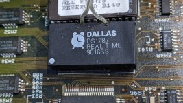
DALLAS DS12887A CMOS battery DEAD on Socket 7 motherboard: A FIX??

TerryKing

Member
Joined
Jun 8, 2022
Messages
20
Location
Topsham, Vermont USA
Hello Everyone,
Many have had this dilemma; mine was worse because I have 3 HOT-555 motherboards with the same SOLDERED IN RTC CMOS CHip.

Eventually I got one to work WITHOUT Soldering.. Take a look here:

https://arduinoinfo.mywikis.net/wiki/DS12887A-DALLAS-RTC-DEAD

Let me know if this works for anyone else!

Regards, Terry King
...In The Woods In Vermont
The one who dies with the most Parts LOSES! WHAT DO YOU NEED??
 
Hi Chuck, Thanks.. your diagrams are great.

It's pretty drastic to Dremel the module. In my case it's almost inaccessible right next to an ISA socket. This is different in using the "Clear CMOS" connection.

IF this works for months with two AA batteries I'll be happy... I'll update my experience.
 
I've done it on boards that were just as tight. Use a small Dremel burr and go slowly. Worst case, you have to remove the RTC chip.

Honestly, I think that soldering that chip in was the mark of a malicious vendor, right up there with soldered in coin cells.
 
QUOTE "soldering that chip in was the mark of a malicious vendor"

Looks like PLANNED Obsolescence. Like "Buy my new motherboards in 15 years when this dies??"

I'm just interested if this easy, No Soldering solution will stand up. My Dremel(s) are at the ready, usually for sharpening my chainsaws. which they do VERY well.
 
Hi Chuck, Thanks.. your diagrams are great.

It's pretty drastic to Dremel the module. In my case it's almost inaccessible right next to an ISA socket. This is different in using the "Clear CMOS" connection.

IF this works for months with two AA batteries I'll be happy... I'll update my experience.
Tight on that ISA slot - but the other side (close to the IDE headers) is the side you need access to. I put grooves above the internal battery connections (which don't extend to the motherboard PCB, as you discovered. Ideally, you want to disconnect the internal battery (I Dremel in to sever the negative terminal lead).

The contacts are just beneath the surface anyway, and you can do leads out once you expose enough metal to solder on to with a small iron and using flux. Disconnecting the expended internal lithium battery is important - you could also buzz the top off the chip as Peter Wendt did on the page that Chuck linked. In a situation where the Dallas (or equivalent) module is soldered in, I will try to affix a battery and leave the module on the board - and only remove it if I mess up getting a replacement battery on it.

55SXCMOS.jpg
 
I'm not sure if this was the first published version, but it's 16 years old.
Peter Wendt (an IBM engineer in Germany) was the first instance I saw online, but that was from me being aware of him on the comp.sys.ibm.ps2.hardware newsgroup.
 
Thanks @Chuck(G) and @IBMMuseum ...
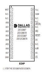
Help me be 100% on what PINS are involved with the Dremel Surgery. The photo above shows a BIOS chip that is 28 pins. But the DALLAS chips are 24 pins. so I'm not sure EXACTLY what pins you have modified. Can you mark or number per this pinout?

Dallas-DS12887A-Pinout.jpg

Probably/Maybe 20 and 16 ?? That's what Chuck's drawing shows... @Chuck(G) may I use your drawings on my WIKI?

I'll pull out another 555 board and look closely...
 
Last edited:
Help me be 100% on what PINS are involved with the Dremel Surgery. The photo above shows a BIOS chip that is 28 pins. But the DALLAS chips are 24 pins. so I'm not sure EXACTLY what pins you have modified. Can you mark or number per this pinout?
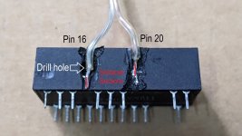
The Dallas module is *next to* a BIOS chip (that's a PS/2 Model 55SX I had right at hand here) - 'Pin 16' (which isn't present, just as a position on the DS1287x)) is the negative battery lead, and 'Pin 20' (also not present) is the positive battery terminal. I use a Dremel to groove a vertical channel (you don't need to go all the way down to the base, to touch the motherboard PCB when it is soldered in) - the resulting "channels" are where the wiring can come up. The internal battery has the negative terminal facing up, so it is easier to sever that lead instead of the positive side to take it out of circuit - Be aware that other compatible module brands might have the battery underneath with the chip die on top (there are even X-ray photos I've seen on the Internet).

I drill in at the top corner of the negative battery lead, then use a multimeter to make sure it is disconnected from where I solder in the lead. Of course, a little bit of flux helps immensely. Having another depleted module to experiment with can be helpful too.

DS1287_1.jpg

BTW, the link that Chuck gave is from Peter Wendt in Germany...
 
Back
Top