• Please review our updated Terms and Rules here

Dallas RTC DS1287 re-battery on Personal Decstation 5000/25

paul

Veteran Member
Joined
Mar 18, 2004
Messages
817
Location
New Zealand
After successful surgery re-batterying all the ST-brand RTCs on my (3) SUNs, I've attempted this on the Dallas part in the DEC, which is slightly more difficult due to the half-baked "bent pin" design, and being soldered in place.

Bottom line is that the computer doesn't boot to firmware reliably and I'm not sure if I've either overheated the chip/crystal or ESDed it, or just have to initialize it. It will not finish POST, i.e. the screen is blank (no scan.) EDIT: Only if I disconnect the cell, after about 20 minutes it comes to life and promptly fails on all the RTC tests.

I used a heat pencil to break down the potting and always had the board wrapped in ESD-safe bubble wrap. Used minimal temp to do the job but the max rating of the part is only 70 C, which I probably exceeded.

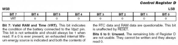
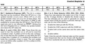
Given that the chip is soldered in place and that DEC didn't expect anyone to change it out, I wonder if the required RTC "wake-up" string is present in the test or boot sequence? See image...

Anyone know anything about this?

Oscillator startup.jpg2014-08-13 22.32.30.jpg2014-08-11 15.23.55.jpg
 
Last edited:
I have reworked 3 Dallas chips (1287 and 12887) on PCs and never had to do something to restart the oscillator.
And IMHO, for computer manufacturers it should be easier (I mean faster and then cheaper) to implement the start sequence in the boot code than to process the chip before mounting it on the board.
 
...but the max rating of the part is only 70 C, which I probably exceeded.
That 70C value likely just the run-time internal thermal rating of the chip... really shouldn't be a critical threshold in de-potting.

The process still could have destroyed the chip but it would have been a lot more heat than that.

It wouldn't hurt to check the solder contacts on the back of the board for those pins that you de-potted closely. You may have heated the solder and formed a solder-bridge across two pins simply by using the heat pencil on them.

I'd expect that there is a command to initialize the RTC but its likely not well documented outside the long-gone factory floor.

I'm curious why they went to all the bother of potting the RTC like that. I had seen some Dallas Semi RTCs that had piggy-backed a battery, crystal or additional ram, but that doesn't appear to be the reason here.
 
Last edited:
Well, I'm still stuck on this problem. Thankfully, at work I have access to a microscope and good soldering kit which is essential as the traces and vias are small and delicate.
I've now installed a new DS12887 and fixed a broken trace which I had accidentally stabbed with the scalpel while performing in-situ surgery on the DS1287. But much to my surprise it still doesn't boot into firmware.

I've now removed the new RTC and checked all surrounding traces and vias visually and found no further damage. I checked to see if it would boot without an RTC installed, which it doesn't.

My next attempt will be to solder in pin sockets and install the old DS1287 with the cell disconnected, let it boot to firmware (which it has done before after about 20 minutes wait) and reconnect the battery. At that point I should be able to issue the wake-up string to the RTC if I can figure out what that is. It's not certain by any means that this is not done on every boot (or test script) by the firmware but I have no other ideas.

One clue I found on the 'net specific to this computer model is how to query the RTC cell condition which uses register D:
However, you may query the chip directly -- the battery state
is reflected in bit 7 of register D of the chip. For the Maxine you can
get to the register by typing:

>> e -bx 0xbc200034

at the console. If the reported value is "0x80", then the battery is OK;
if it's "0x00", then the battery failed.

But what I need to do to wake up the RTC is write a pattern of 010 in bits 4 to 6 of Register A. Writing to memory uses the "d" command instead of "e".

Does anyone recognise the address format and could offer a clue as to what the command might be?

For reference, from the DecStation docs:

d Command
Use the d command to deposit values in memory. The d command format is
d [-(b | h | w)] [-S count] rng

Use one of the optional parameters -(b | h | w) to specify whether to deposit the contents as bytes, halfwords, or words.
Specify -b to deposit the contents as bytes.
Specify -h to deposit the contents as halfwords.
Specify -w to deposit the contents as words.

Include the optional -Scount parameter to store the same value more than once. Replace count with the number of
times you want the value to be stored.

Use the rng parameter to set the range of addresses across which the values are stored.
To deposit values at a single address, replace rng with that address.
To deposit a number of values across a range of addresses, replace rng with the address range. Use the form
address_low :address_high to define the range. Replace address_low with the starting address for storing values and replace address_
high with the ending address for storing values.

To deposit values at a series of addresses, replace rng with the starting address and the number of successive
addresses at which you want to store values. Use the form
address_low#count to specify the addresses where you store values. Replace address_low with the starting address for
storing values. Replace count with the number of values you want to store.

To specify more than one address range, separate the range specifications with commas. Leave no spaces
between the range specifications.
 

Attachments

  • regD.jpg
    regD.jpg
    24.8 KB · Views: 1
  • regA.jpg
    regA.jpg
    30.8 KB · Views: 1
Back
Top