• Please review our updated Terms and Rules here

Dead 2001

Let's just wait for confirmation from @Hugo Holden or @dave_m regarding the EPROM compatibility issue before trying it...

The 2532 should be a a drop-in replacement as pin 18 on the EPROM is actually A11.
daver, you are correct about the issue with 2516's not good replacements for 2316 ROMs in sockets H5, H6 and H7 due to pin 18 chip enable polarity (CS2).

And yes the 2532 can be used with 4K images to replace BASIC 2 in either sockets H1, H2, and H4 for C, D and F ROMs or in sockets H5, H6, and H7 as Jannie has stated.
 
Bit of an update:

Keyboard was mostly non-responsive and I already had visions of doing the silver paint thing. But gave the copper and carbon a good clean and it seems to be working fine. The carbon pads on the Return key measures between 1 and 2Kohm while most of the other keys are closer to about 400ohm, but it seems to be within the tolerance to be reliably detected. Guess the two in parallel helps.

With the keyboard working I started testing the PIAs and VIA, basically the cassette and IEEE ports. Got a bunch of intermittent errors, to the point that I suspected the sockets, so replaced all 3 the 40-pin sockets. They were definitely shot. Two pins literally fell off during desoldering and the leaves were heavily corroded.

With that out of the way, I still errors such as multiple characters randomly returned for a key press, the PIA pulling down the level on the cassette read and the system randomly dropping to the monitor during a load from CASS2. Swapping the PIAs around showed that different bits in both are broken. Replaced PIAs with new 6821s and also put a new 6522 in.

At this point the keyboard, and two cassette ports seems fine but got a bad ATN result from running the IEEE test program.
(I originally create the IEEE test program on a 8032 and the output is all upper case, so the 2001 merrily displays all messages in PETSCII :) )

ATN is controlled by both a PIA (B8) and the VIA (A5), and with both those replaced I assumed the relevant buffer in A9 must be faulty so socketed and replaced it. Still getting the "ATN is Bad" error though, so need to think what could be causing it. I was confident enough that it must be the MC3446 that I did not measure around it before removing it, having had similar symptoms and causes in previous systems.

. Any ideas on this would be appreciated.

BTW, I need to get an "SD Drive" to use with the various PETs. Any recommendations on the current favorites in terms of price/performance/compatibility/ etc.?
 
The VIA (port B bit 2) drives /ATN OUT.

The PIA (#2) responds to /ATN IN.

Look at the PET IEEE488 port manual that the test program came from.

You should be able to manually enter the POKEs to drive /ATN OUT and measure the voltages at:

A5/12.
A9/13.
A9/14.
A9/15.
B8/40.

It is important to check at each end of the PCB tracks - to rule out a PCB track fault.

Drive the output first to one state and then to another and make sure that the voltages change at every point. Where the voltages stop changing, there be the fault...

This will test the VIA output - but you will then have to look in the manual for the PEEKs and POKEs to test out the PIA input.

It is important to put the effort into doing the checks before warming up the soldering iron. In a large majority of cases, it will be the silicon that is at fault - so swapping A9 out would clear the fault in 80% of the cases. However, you then end up with the 20% of the cases where it doesn't...

Practicing the voltage checks takes a bit longer, but gets you into the mindset of finding the real cause before you wield the soldering iron.

Dave
 
Last thing on the list, for this 2001, is the 9" monitor. Going to tackle that tomorrow.

Any tips I should first look at before firing it up?

Also, most common issues I might run into?

BTW, I assume I can just inject around 14/15V DC into the AC feed to the monitor?
 
>>> Any tips I should first look at before firing it up?

>>> BTW, I assume I can just inject around 14/15V DC into the AC feed to the monitor?

Before you do ANYTHING you need to clearly identify exactly what monitor you have. There were at least 3 designs for the 2001...

Dave
 
Last thing on the list, for this 2001, is the 9" monitor. Going to tackle that tomorrow.

Any tips I should first look at before firing it up?

Also, most common issues I might run into?

BTW, I assume I can just inject around 14/15V DC into the AC feed to the monitor?

If you inject DC at least it is fairly safe because the bridge rectifier in the VDU will prevent any problems with the input polarity. But, it is not a great idea because doing this doesn't check fully that your input rectifiers and input filter capacitor prior to the regulator. Some VDU's, the 12" versions, had an 18V regulator too, so like Daver2 says make sure you have the correct schematic for your VDU.

All in all I would simply power the VDU from the AC supply from the transformer that it naturally receives in use to test it. You need to have the VDU near the working computer anyway, so that it receives its H drive, V drive and video signals. These are not like other common garden VDU's, they have no scan oscillators and rely on the H and V drive signals from the computer to operate. For example if there is no H drive, there is no EHT and no auxiliary voltages from the H output transformer. If there is no V drive the vertical scan is collapsed.

It is easily possible to make a small sub board with oscillators on it to produce the correct drive signals for isolated VDU testing, independent of the PET computer motherboard, but I have not seen anyone do this yet probably because it is more convenient to use the computer signals that suit the task.

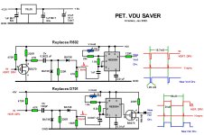
A while back I designed a VDU saver for the 9" PET and tested it on a proto board, it is wired in by lifting one diode and one resistor. It gifts the PET VDU with its own scan oscillators, which then synchronize to the drive signals. So that the drive signals could be grossly abnormal and no harm would come to the VDU. This would also work for independent VDU testing, and an oscillator could be used to generate some bars to test the video too.

However, since the main opportunity for damage to the VDU is an abnormal H drive signal, I simply settled in the end for power Zener diode protection on the horizontal output transistor's collector circuit.
 

Attachments

  • PETVDUSAVER.jpg
    PETVDUSAVER.jpg
    264 KB · Views: 9
Last edited:
Hey, got side-tracked (read ambushed) by the wife this morning to fix the lawnmower and weed eater (I don't know how she manages to break them all the time! :biggrin:), so first had to get to that.

@daver2 , @Hugo Holden:
1. It's a 320034-02(F) board - of the 3 circuits on zimmers, there's a 320032 and 320033. The video-1.gif does not seem to have a model number associated, so not sure if it is the 34. Which circuit would be closest to the 34?
2. It's a 110V PET, so to use the transformer, I need to put a 220/110 step-down transformer in front of it. Which I can do but it gets clunky on the bench. So far I just put 8V DC straight onto the main board for repairs. Got a 4-output variable PSU, so can easily feed the 12V regulator on the video board with 14V at the same time. (With the dynamic PETs, I inject all 3 voltages to work on them.). @Hugo Holden , guess one could effectivity test the DC circuit by swapping the external DC feed polarity (on the AC input). But a simple diode test on the rectifier diodes would achieve the same.
3. I've also contemplated building a small 'video tester' generator to inject something like a checkerboard or vertical bars pattern into either the 9" or 12" monitors. But for now, I will use the board as a generator. (Though, any excuse to make more test kit is always highly enticing :) ).
.
Any tips before I fire it up? A visual inspection does not show anything untoward.
 
Last edited:
I would disconnect the transformer from both the logic board and the monitor. The monitor has a plug and socket inside the monitor itself.

If you power it up you should be able to measure the correct AC voltages on the secondary of the transformer. Do you have a multimeter?

Dave
 
I would disconnect the transformer from both the logic board and the monitor. The monitor has a plug and socket inside the monitor itself.

If you power it up you should be able to measure the correct AC voltages on the secondary of the transformer. Do you have a multimeter?

Dave
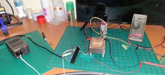
All the secondary voltages looks good. But, as mentioned above, it's a 110V primary, so I have to use a stepdown (black box to the left) to use it on 220 mains.

110V.jpg

I also brought the 27000uF cap slowly up to 15V using a series resistor to limit the charge current to max 5mA. Never done this "reforming" thing before, but thought it could not hurt. The cap seems fine, literally holds its charge overnight and the leakage current at 15V is a few micro-Amps.

I can definitely plug the whole setup (board plus video) into the original transformer + stepdown - as in the above pic - but, as mentioned, it takes up a lot of space and, of course, you need to be careful with the exposed mains voltages. Thus me powering the boards from the DC supply which is more out of the way.

Another question: When working on the monitor, is it easiest to take the CRT out the metal casing? Seems so with the difficult access to get the HT lead in and out the tube while still in the case. If so, how do you normally support / protect the CRT while out the case?
 
If you have already checked the secondary voltages - go for it!

I (personally) would not take the monitor out of the case. I would leave everything inside until I know what is going on.

The other way of doing it (which may fit your current arrangement) is to leave the monitor out of the equation for the time being and just power up the logic board.

The first job is to make sure the black magic smoke does not escape.

The second job is to check all of the low voltage DC power rails from the on board regulators.

The third job is to check for signs of vertical, horizontal and video signals on the video connector with an oscilloscope.

I would also check the 6502 CPU pin 7 for signs of activity. This pin pulsing indicates that the CPU is fetching (and executing) valid instructions.

If the monitor signals are all present, then reassemble the system and test with the monitor to see what we have...

Dave
Methinks you suffered from an NMI calling an undefined vector..... 😄

This machine is still the same one that is the subject of this thread, a (used to be) dead 2001.

In the posts above, we fixed the main board, so that's all working. Also refurbished the PSU and keyboard, so they good as well. Must still do the cassette player. In the mean time I'm using an external C64 cassette and I should get an SD Card disk drive tomorrow to fully test the IEEE bus.

So, the last thing on the list is the monitor. 🙂

I'll power it up tomorrow and see what we get. Off to the theater now to go watch some Queen.

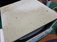
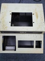
PS: The CRT will need to come out at some point as the machine needs a complete repaint, with, unfortunately, significant rust.
 
Last edited:
I am trying to repair multiple PETs, do two jobs at Church, the washing up, the gardening and I have just had a high priority NMI from work!

You're obviously correct of course...

Dave
 
I am trying to repair multiple PETs, do two jobs at Church, the washing up, the gardening and I have just had a high priority NMI from work!

You're obviously correct of course...

Dave
I mostly forget why I'm doing something, let alone what I'm supposed to be doing.....🙄
 
PS: The CRT will need to come out at some point as the machine needs a complete repaint, with, unfortunately, significant rust.

There are lots of tips in this article I wrote on restoring PET VDU's, including a stand for the CRT when it is out of the cabinet (pg 12) and how to deal with the rust. There are a number of suggested modifications, the main one that is easy to do, for the 9" PETs that have the issue, is to alter the value of a capacitor to prevent the turn off spot.

www.worldphaco.com/uploads/RESTORING%20THE%20%20PET%20COMPUTER%209.pdf
Thanks @hugo. I have, indeed read your most excellent writeup before, specifically around the spot reduction section. Of course, now that it's pertinent, one tends to read it with new eyes. I forgot about the stand section.
 
An update on the /ATN issue I found above on the IEEE bus.
.
To recap; in fixing this 2001, I replaced all three the IO Chips (all confirmed faulty) but when I ran the GPIB Tester program, it failed the /ATN signal. I thus replaced the relevant IEEE bus transceiver, but that did not fix the error reported when running the GPIB Tester program, it still reported /ATN as faulty.
.
After checking all the signals for continuity, and with a scope, I decided to switch to BASIC 4 (the 2001 is running BASIC 2) as I could not see any obvious faults. Lo and behold, with BASIC 4, the program passed the /ATN signal. Then checked BASIC 1 and it also passed. Confirmed BASIC 2 fails it every time.
.
Using an SD Drive emulator, shows that the IEEE bus seems to be working fine and I can load, and run, software from the external drive, no problem. This on BASIC 2 and 4.
.
In summary:
The GPIB Test fails the /ATN signal on BASIC 2 but passed it on BASIC 1 and BASIC 4
An drive plugged into the IEEE port works fine on both BASIC 2 and BASIC 4.
.
This is the second anomaly I picked up with BASIC 2 in this repair. Earlier in this thread we saw that BASIC 2 would not display a screen (while BASIC 4 would) with a faulty VIA and now we have a scenario where BASIC 2 fails an IEEE signal while BASIC 4 passes it, no problem.
 
Hmm, I am wondering whether you have a faulty BASIC 2 ROM somewhere - just a thought in passing...

Also, beware of early versions of BASIC if using the IEEE488 port - they were so buggy as to be unusable...

I am not sure why your /ATN issue is related to the actual version of BASIC - as the test program just uses PEEK and POKE commands directly on the PIA and VIA. The test program doesn't even use the BASIC IEEE488 functions.

I assume we are talking about the same test program of course...

Dave
 
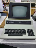
Happy to report that this 2001 is now fully functional. :love:
.
With the help of this forum, we determined that the following was faulty and was replaced:
.
- 7408 in the video circuit
- All the SRAM, all 18 of the 2114s.
- All the ROMs
- All 3 the IO chips
- All the 40-pin sockets
.
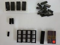
3 chips were replaced that were likely not faulty but testing pointed to them; 2 x 244 and a IEEE transceiver.
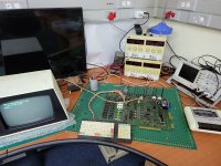
Fixed-20.jpg
.
With all these replaced, all functions tests good and the machine is fully working. Woot!!!
Fixed-02.jpg
.
Next is to have the casing repainted and then to reassemble everything. I will keep this machine on BASIC 2, even if that seems to introduce a number of limitations.
Fixed-40.jpg
Fixed-42.jpg
.
Thanks to everyone who helped on this thread!
.
Next on the bench is this 3032, will open a new thread for this one. :)
20230527_183033.jpg
 
Hmm, I am wondering whether you have a faulty BASIC 2 ROM somewhere - just a thought in passing...

Also, beware of early versions of BASIC if using the IEEE488 port - they were so buggy as to be unusable...

I am not sure why your /ATN issue is related to the actual version of BASIC - as the test program just uses PEEK and POKE commands directly on the PIA and VIA. The test program doesn't even use the BASIC IEEE488 functions.

I assume we are talking about the same test program of course...

Dave
Yup, the one in the IEEE book. Defintely only PEEK and POKE the IO chips.
.
I've confirmed this with my own Welte ROM board, a Tynemouth board and the ROMs plugged straight onto the board. So pretty sure it a BASIC 2 thing.
.
My working hypothesis is that BASIC 2 initialises the IO chips differently and that leads to the symptoms observed.
 
Back
Top