KLund1
Veteran Member
Hi again,
I have a Type 1 5170 motherboard with U27=6181028, U47=6181029 BIOS Roms.
Sadly if does not boot.
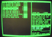
I have a Post code card I just remember I had. I get 0201 on power up. I get no beeps
There was a 16mhz crystal installed, and a 12mhz taped to one of the chips. I put the 12mhz in for this testing. The 16mhz legs were bent in half to fit in and one broke off when I was gently removing it. But since I get some post code the 12mhz should be working ?
I looked at the always helpful munuszerodegrees site and there was no troubleshooting for a 5170.
what to test for next?
Thanks
I have a Type 1 5170 motherboard with U27=6181028, U47=6181029 BIOS Roms.
Sadly if does not boot.
I have a Post code card I just remember I had. I get 0201 on power up. I get no beeps
There was a 16mhz crystal installed, and a 12mhz taped to one of the chips. I put the 12mhz in for this testing. The 16mhz legs were bent in half to fit in and one broke off when I was gently removing it. But since I get some post code the 12mhz should be working ?
I looked at the always helpful munuszerodegrees site and there was no troubleshooting for a 5170.
what to test for next?
Thanks