• Please review our updated Terms and Rules here

Fat 40

Gary C

Veteran Member
Joined
May 26, 2018
Messages
2,297
Location
Lancashire, UK
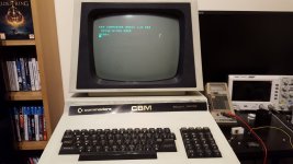
Next up is a 4032 fat 40.

Power up and all transformer voltages present and correct, plugged into the board and +4.97, -5.06 & +11.9 so not anything to worry about

But nothing on the screen but a raster with the brightness turned up.

Quick off & on and the normal pet garbage is show for the briefest of moments then nothing.

Scope on 6502 pin 7 shows healthy activity so it doesn't look as if its crashed.

PETTEST installed, and everything looks fine except the keyboard input is showing FC FC FC FC FC FC FC and will only change when some keys are pressed.


Scoping on UB12 PIA its noticeable that the lines PA0 to PA3 are sat at high, high, low, low and arent changing which isn't right.

Not sure why that would stop the startup process but first, change the 6520 and get PETTEST to work as it should. Interestingly this is the second 6520 I have had a port failure on this month and I am still awaiting parts to repair the SK. I am thinking the 65C21N might be a better choice going forwards so I have 4 on order from Mouser.
 
Humm, whats the thinking

As PETTEST runs to the keyboard test and shows some changes, Im assuming port B of C13 is working but port A doesn't do anything.
 
The 6520 PIA was/is clearly hosed if you were getting FC returned (or you had some short circuits in the keyboard matrix somewhere). Unlikely with the number of logic 1's in FC though...

I was more thinking of your original problem:

>>> Quick off & on and the normal pet garbage is show for the briefest of moments then nothing.

The EDIT ROM will clear the screen (hence the garbage to blank screen). The RAM must be working (as I assume you have let my PETTESTER do a number of DRAM test passes)? I further assume that my PETTESTER has given the ROM checksums a clean bill of health?

This just leaves the EDIT ROM itself or a potential 'funny' with the /IRQ line. The /IRQ line can potentially cause the machine to 'hang' indefinitely (if I remember correctly).

That's my thought process anyhow.

I see the modification I was involved in saved 3/4 of the money last week :)!

Dave
 
Yep

Finally tested it. Saved a few million and more importantly meant I didn't need to work late that day.

Not only that, the transient was so well controlled because it saw it early, we didn't come anywhere near the limit.

Edit ROM checks out in my programmer so its not that.

If there was an IRQ being held low, that would stop PETTEST too ? Ah, because IRQ's aren't enabled in PETTEST ?
 
If I was allowed to modify the software - I could have got the auto control system to have responded a second (or so) earlier. It doesn't sound like much - but it would have given us still more margin and less transient...

I did suggest we share 1% of the money we saved for a party...

Correct - PETTESTER never enables the interrupts.

It was all getting much too complicated to organise for one executable to work with all the possible versions of the Kernel ROM - and then throw in all the possible versions of the /IRQ entry point as well!

I am looking at a 4K version if the new PETTESTER lives at $Fxxx - as I now have control over the NMI, IRQ and SWI vectors in addition to the RESET vector...

Dave
 
Ooh, good call

IRQ is low and never goes high during reset.

Hopefully its B12 holding low which would be nice.


I think we only got about a 7C increase which is nothing, was also a 10s worst case and it handled it beautifully. The only problem was the NRG still trips. We modded the code in the 90's to keep it in auto during runback, but it probably could do with a post runback inhibit too.
 
Yes a 0xF PETTEST would have lots of advantages but loose the main one of sitting in a socket but it would be a very worth while addition as a more complete tester.
 
>>> Ooh, good call

OPEX...

I will make the 4K enhancements a conditional assembly option - so you have the choice...

Dave
 
B2 6520 removed and IRQ now high and with the EDIT ROM back in, it runs to the start up message :)

Just need the new PIA's to turn up.

I have some Rockwell 6520's on order but did order a W65C21 as suggested on here but just noticed its the S version not the N version. Looking at the spec I can't see why it wouldn't work but does anyone else know ?
I do have an N version (with the rate they have been failing, I though I should get a few while the WD versions are cheap) on order so I can at least try both.
 
Yay, Chip(s) arrived. One Rockwell 6520 and four W65C21N's.

Socketed B2 and both types of chip tested and work perfectly. Disk interface checked and is also working but I dont have the tape drive at home to test.

Next job is to clean the case and re-attach the badly stuck on label.

1681326083738.jpeg
 
Last edited:
And its dead again.

Makes the chirps on power up, but nothing on the screen and no raster with the brightness turned up :(

Horizontal, vertical & video present, 200V on Q721 so the LOP should be being driven so should have anode EHT, heater is on. LOPT coils all show conductivity.

No 400V for G2 which sounds familiar, R752 is open circuit !
 
It may also indicate that the resistor is potentially running hot because there is slightly too much current flowing through it?

Perhaps if it fails again you measure the current flowing through it and have a look at the components downstream of it.

Dave
 
Oh, of course that's true, but it seems fine with a new resistor its nice and cool though I have not especially checked the current, just age I suspect and its the second one in two machines and I believe its reasonably common ?
 
So this machines disk drive is a 8050 and while its lights do the dance and drive 1 seems to format ok, drive 0 wont work. When a disk is inserted, it only occasionally spins. The microswitch is fine, the motor and hub spin freely, but oddly the motor will run if you give it a flick when you click the microswitch.

Motor stripped (a micro puller is essential to remove the hub and so it catching the brushes and springs) and the little springs behind the brushes have corroded slightly and jammed so there is no pressure on the brushes. The commutator has also picked up a bit of wear due to the light contact and excessive sparking but a light buff has resolved it.

Just need to reassemble. Trick is to reassemble the rotor into the bottom bearing then insert the bushes, then the springs into the back of the holders and close the flap. Then its important to insert a stick down through the stator onto the rotor as you insert it to stop the magnet from pulling it out of the brush holders and allowing them to shoot out.

Love a simple mechanical fault.
 
Last edited:
Back
Top