• Please review our updated Terms and Rules here

Four-Phase Systems IV/90

For the LM319, yes.

hkjgjh.JPG
 
Go back and read #16. He's talking about four different issues--dried out capacitors, a crunched LM319 DIP, a roadkill diode and a TO92 transistor. :)

I suspect that this will be a big job. After all of the obviously damaged components have been repaired, there are probably several "soft" failures of components that look physically fine, but have died.
 
MITA has offered to conditionally loan out almost any board I need for comparison and testing, so for when I don't have schematics I at least have test parts in better condition that would let me bring up a base model IV/70. For now though I just need to see everything receive power and not explode which also involves attempting to repair any damage found during the cleaning/inspection. Actually seeing life out of the IV/90 at this point would be wonderful.

Edited: keep in mind those parts might not be JFET's. That's just what the $25 component tester *thinks* it is. I should ask MITA if they can verify what their board has.
 
Last edited:
Replaced all of the troublesome 50uf 50v capacitors, tested for shorts and ran the smoke tests.

+5, -5, -22 and -28 all came up at the test points and nothing seemed to explode for about a minute, then I got the smell of something hot and a quiet *pop*.
I don't see anything on the boards having blown this time and the smell doesn't get worse when I take the bottom off and check the connections around the backplane so something in the power supply must of popped, but none of the rails are reading out of spec and the large lytics I already reformed. I got two options. Pull the power supply out again and check it over again or assume a tantalum buried somewhere blew open and we can continue testing.
It's a linear supply, so there is not a lot to fail but it does still have some regulation attached to it, so I'm not sure if it's too smart to test completely unloaded.
 
Neither. I got fooled by the fans again.
Sniff test found that a 2N3643 had blown apart on the IV DT board. I didn't see it at first but when I went to drop the board back in a second time I found one half of the transistor stuck in the slot, then I spotted it in the farm of identical transistors.

CGS_11685.JPG

CGS_11686.JPG


The AC filtering however you make a good point about, however it doesn't actually have any. There is however a massive inline filter that lives inside the PDU.

I'm going to bring out the thermal imaging camera and do a hotspot test. This is starting to get annoying however given where this had been stored a pile of failed parts is still possible.
 
Last edited:
On further testing with the thermal camera I found the neighboring resistor network DIP (seen lower left with "122F" visible) and all the transistors in that bank were getting really warm. Something's either overdriving them or shorted out somewhere. I've pulled the board for now. With the board installed the machine draws 427w. With it pulled it goes down to 275w. I find it hard to believe that this one board with no heatsinks eats roughly 150w.

11003102-B-fr_sm.JPG


Found that the B3*PE and CPE indicator LED's were broken on one of the boards. Split the casings and replaced the LED's with identical parts from Dialight 555-4007 ganged LED indicators.

None of the ram is also getting warm. Each board has multiple test points, including ground and Vss and that reads 0.65v, which is weird because the four voltages they give you test points for on the back of the PSU are all there. What is even weirder is the Vss test point does go to pin 1 on every memory chip (no datasheet) but on every board it does not directly go to a pin on the edge connector and continuity between Vss points on multiple boards doesn't exist either....and there's no local regulation. You have one pin with a 1/4 watt 1K resistor and a small diode. If that's for power they built the boards to handle a lot of current on that trace and it's everywhere and that power has to some from somehwere. I'll poke at the PSU output voltages and verify the backplane rails have not separated from their wires.

11003891-A-fr_sm.JPG

11003891-A-bk_sm.JPG
 
Last edited:
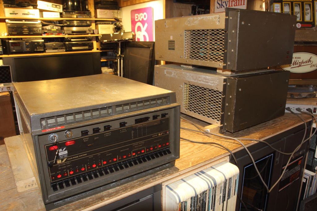
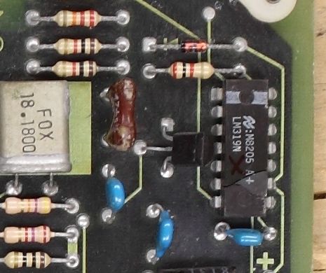
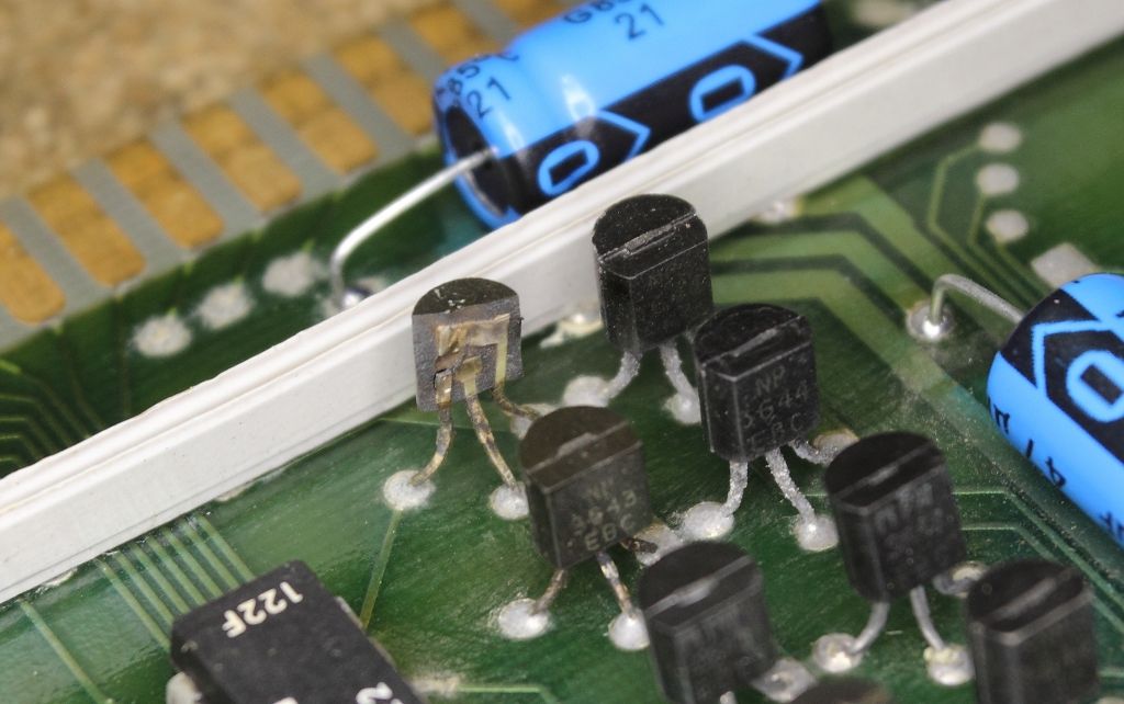
Well diagnosing WHY the transistor exploded was fun.
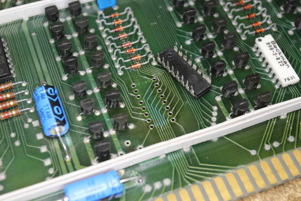
So I started by removing the resistor network, then I was able to check the group of diodes. They tested fine. I ahve not tested the network but I'm guessing that's fine too.

CGS_11687.JPG


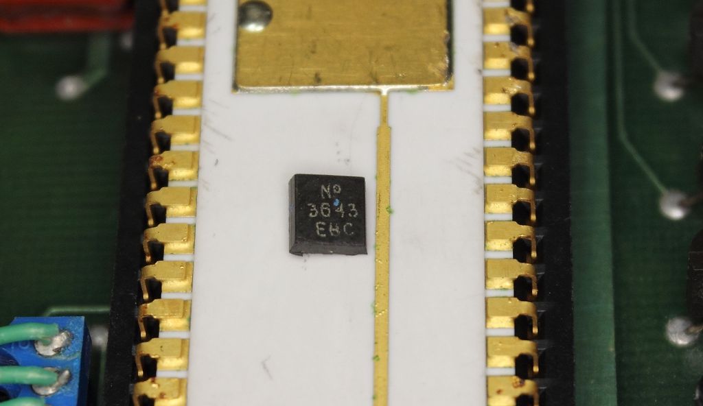
With that removed I plugged it back in and let it cook for 20 seconds with the power on. The thermal camera now saw a single 2N3643 transistor in the lineup that was abnormally warm. Pulled it out and it tested fine. Huh...
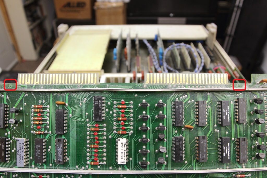
So each 2N3643 in the lineup is complimented by a 2N3644 next to it. I'm not entirely sure why but there's two other similar banks of transistors like this with a row of diodes and a resistor network so I can only guess my fault might be in these transistors, should any be leaking and driving the other transistor next to it to the point of blowing up.

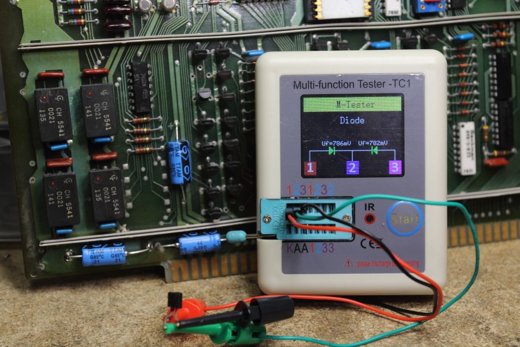
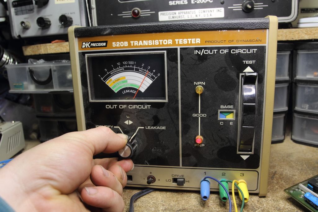
Found two that were bad. One read as two diodes, the other (that was paired with the first transistor that blew up) was so thwacked it was putting the tester into self-test mode, so I put it into the BK Precision tester and it saw it as VERY leaky.

CGS_11689.JPG

CGS_11688.JPG


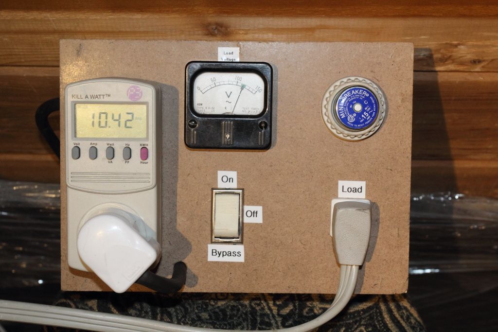
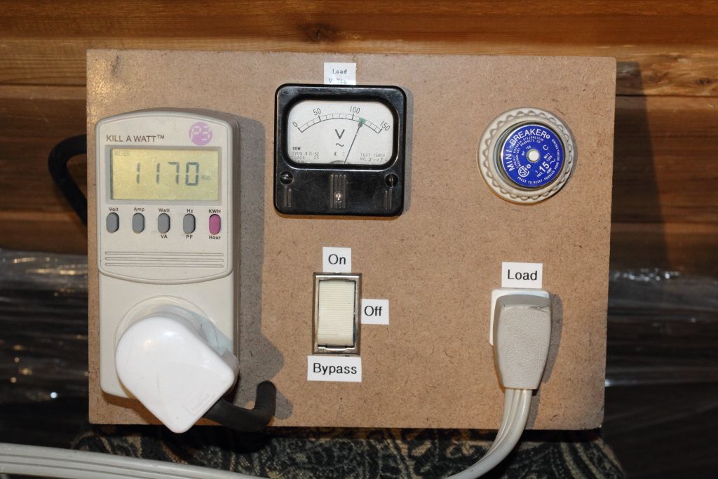
Alright well that would explain why the transistors were unhappy. So I pulled out three bad transistors in all, put the resistor network back in and put that back in the machine and let it soak for another 30 seconds. Pulled it out and found two more transistors that were getting hot along with the network. Neither had tested bad previous but one I had already marked as our original transistor that I saw getting hot and I had since moved it to a different location and the fault moved with it, so it these must be damaged in some way the tester can't catch. After pulling those I ran it for another minute and the thermal camera no longer found any more hotspots or an overheating resistor network.
So in all, six bad transistors to be replaced. Three 1N3643's and three 2N3644's.

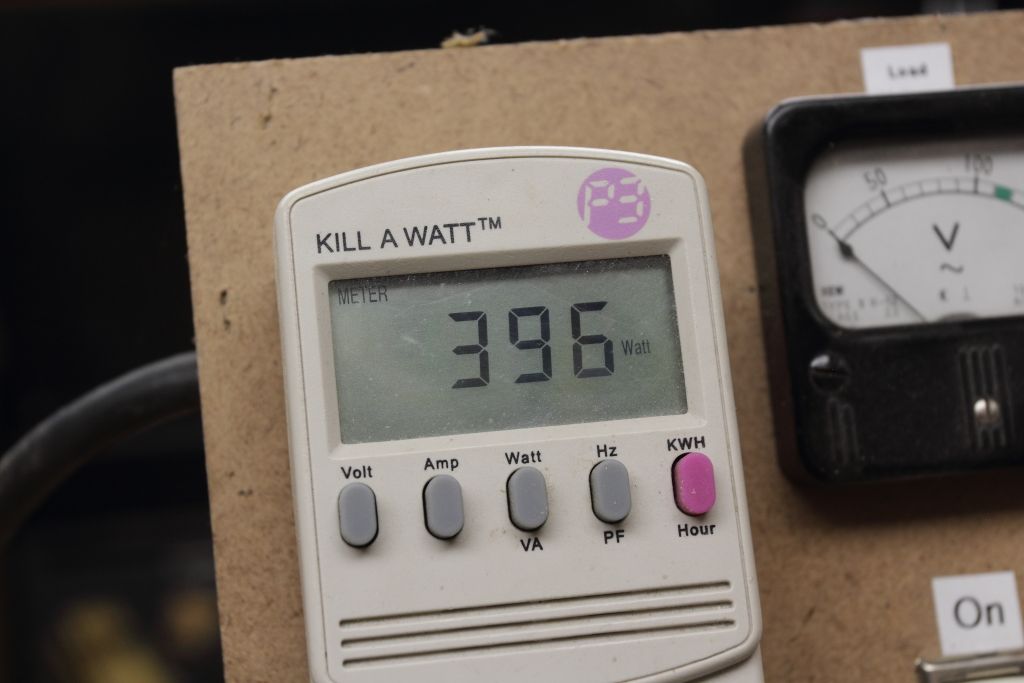
Edited: well even though we got a bunch of transistors now missing the machine has now passed a five minute run test without burning up again so I'll oil the main fans, fabricate a cover for the machine and put it in for an extended burn-in.
 
Last edited:
Progress!

The top lid on the machine has been missing since I got it. Turns out it's exactly the same as the bottom cover. For the sake of testing I'm putting the bottom cover on the top so I get correct airflow. I wonder if I can find a metal shop locally I can take it to as a template and have them make me another one. It's two bends and four holes in a sheet of aluminum.
I've got the box powered up and running just so I can work some oil into the two rear fans because one's pretty chattery. The system is still disconnected from the IV/90 cabinet so nothing works but I don't think leaving the bus in that state really hurts anything. Not much I can do until I get those transistors replaced, I think.

CGS_11690.JPG

CGS_11693.JPG


Now some cosmetic questions. First is that the front panel is normally held in by a pair of plastic push/pull pins. One is missing and the other is getting ready to fall apart. Does anyone know the proper name for these?

CGS_11694.JPG


The other thing is it looks like the light shroud for each indicator has slipped on the front panel so each indicator has a shadow. How would I correct this? It's adhered to the silkscreening so if I'm not careful it would just rip the paint off.

CGS_11691.JPG

CGS_11692.JPG
 
I've heard the fasteners called "push rivets" and they're used in autos for things such as fan shrouds and wheel fairings. Just google on "push rivet" and you should get a lot of hits. Grainger even has the generic ones.

As far as the LED shroud goes, it look looks pretty firmly attached to the faceplate. I wonder if the issue isn't slipping so much as the mispositioning of the board that carries the LEDs.
 
Actually, the front panel is incandescent. Tiny little bulbs all in sockets and most were burned out when I tested them. They're all replaced now so the on/off pattern on the panel is just how it wants to default the display and not me staggering duds or something. :p
I'll double check again though in case the mounts were misaligned or something.

Yeah I thought they were push rivets as well but those are typically one-time pieces or used screw heads. These are more like the push/pull latches you found in the early PS/2's. They might be called "push/pull" or "knob rivets". This is the closest thing I've seen so far but they aren't available in any small quantity - https://www.globalsources.com/Plastic-rivet/Pin-Snap-Rivet-1145800292p.htm
 
Last edited:
Here we go. Fixing computers with motorcycle parts.

"HONDA CBR/TRX PLASTIC RIVETS PULL LATCH CLIPS"


That at least gives me a local place the check.
 
The IV/70 chassis, the IV/90 and the NP80 are now passing smoke tests. They're pretty hungry.

CGS_11749.JPG

CGS_11748.JPG

CGS_11747.JPG


So now I'm trying to figure out the cabling that links the expander board in the IV/70 to the IV/90 chassis. Since I don't have an original IV/70 boardset we can't proceed until the two are reconnected and it uses two long shielded 50 pin ribbon cables which lack absolutely any keying on either end. All we got to deal with is markings written in sharpie many many years ago.

front.jpg

rear.jpg


Well FRONT and REAR make sense for the IV/70 since the expander board has two identical edge connectors. Except that the FRONT cable also has J3 written on it, whereas the front connector on the board is marked J4.
The REAR connector has J4 written on it and that edge connector is...yep, J3.

CGS_11740.JPG

IMG_5100.JPG


Now we get to have fun with the other end which has yet more markings and somehow makes somewhat more sense.
The IV/90 connector for both cables has J1 through J4 marked. J1 and J2 are actually internal to the cabinet while J3 and J4 face outwards. One cable has J2 written on one side and J4 on the underside, so that must be the lower connector. The other cable has J3 written on the top, so presumably this is the upper connector with this side of the cable facing up....I think. @_@

CGS_11736.JPG

CGS_11739.JPG


This is stupid. I can't tell which way is the correct way and we can see on the expander board that the pinout isn't identical, so there's a high chance you'll plug it in wrong and god knows what. Instead of marking the connector names with a sharpie they could of just marked them with offset lines across the connectors, that way you know the orientation and location. t(.o.t)

Well I need to look into cleaning the connectors now. HAving sat upside down it seems moisture was allowed to collect in them and they are pretty crusty.
 
IMG_5108.JPG


*sigh*

The connectors are too water damaged to be reused and the fingers are falling out. I do not have crimp IDC ribbon to double sided 50 pin edge with rigid panel tabs on the sides and do now know where to find them anymore for cheap.
The shielded ribbon cable also has really crusty ends. I might have to cut the cable back six inches and see how far in the corrosion has reached.
 
They are 3M. I'm still trying to find a part number on them.
I still got a few of these salvaged from you years ago (thank you btw) but they lack the extra bolt holes. which is needed for the cable shielding.
 
Last edited:
Back
Top