• Please review our updated Terms and Rules here

Fun with Ti-74s - I2C

JGardner

Experienced Member
Joined
Jun 14, 2009
Messages
200
Many useful chips use the I2C com protocol; the '74 is quite capable of dealing with

them.


An example is the highly accurate DS3231 Real-Time-Clock eval board from Macetech:

http://docs.macetech.com/doku.php/chronodot_v2.0.

The chip is available in SOIC from Digikey, for those who deal in surface mount ICs;

not difficult really, but I'm an old man, so I did it the easy way... :)


So how accurate is it? Well, DS claims 30 seconds/year - Observed deviation in this app

with my parts amounts to ~ 1 sec/month - YMMV, but not too shabby.


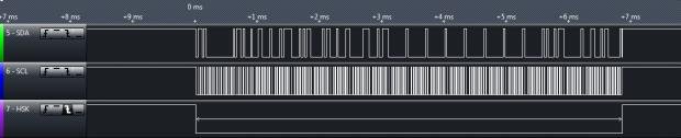
So on to I2C - It's a Synchronous Serial protocol, which means that there is a data line,

and a clock line - Data is transferred in sync with the clock line, so the protocol does

not suffer from the limitations of inferred time-keeping, like, say. RS-232, including

being locked in to specific data transfer rates, 57.6K Baud, say...


In particular, there is no <lower> speed limit - You can do I2c directly from BASIC if

you wish - <Very> slow, but it works.


I2C is a Master - Slave protocol - The master transmits 1st, and controls the clock.


A confusion factor for those new to I2C is that data is transferred on <both> edges of

the clock signal - The Master transmits a bit on the leading edge of the clock, and

receives a bit on the trailing edge.


I'll be back tomorrow or the next day with explicit instructions & code examples.


Have fun,

Jack
 
Excellent I2C tutorial: http://www.robot-electronics.co.uk/acatalog/I2C_Tutorial.html

Macetech Chronodot data sheet: http://docs.macetech.com/doku.php/chronodot_v2.0

DS3231 RTC data sheet: http://datasheets.maxim-ic.com/en/ds/DS3231.pdf


You'll need these to make sense of the forthcoming code example. But first -


Connecting the Chronodot to a TI-74:

1st, the "Dockbus" pinout on the TI-74...

Set the 74 down in front of you, display up, with the keyboard toward you. Turn it 180 degrees, so that the

keyboard is now away from you. You'll see a 10-pin male connector inset in the back of the 74. From left to

right, the pinout is:

#1 - Power Out (~ +5 VDC)
#2 - Power In
#3 - Data 0 ( d0 )
#4 - Data 1 ( d1 )
#5 - Data 2 ( d2 )
#6 - Data 3 ( d3 )
#7 - HSK
#8 - BAV
#9 - RESET
#10 - Ground


Referrring to the Chronodot docs (or the board itself) you'll see the connections on one side are marked:

SDA - Serial Data I/O
SCL - Serial Clock
VCC - Power In
GND - Self-Explanatory - I hope... :)

Connections are as follows:

TI-74, Pin 1 -> Chronodot, VCC
TI-74, Pin 3 -> Chronodot, SDA
TI-74, Pin 4 -> Chronodot, SCL
TI-74, Pin 10 -> Chronodot, GND

My setup uses a small breadboard, 6"/75mm jumpers with female receptacles, and .100 headers, sold

by AdaFruit, Pololu, & many others - Some representative links:

breadboard - http://www.adafruit.com/products/64
jumpers - http://www.adafruit.com/products/266
headers - http://www.adafruit.com/products/400

Needless to say, there are other ways to do this - Just don't reverse power & ground!

... more to come ...
 
Watching this one develop with much interest! Thanks for the detailed research here.
 
Kind words, Sir - Thanks... :)

Attached is a TI-74 pgm which will read a connected Chronodot 2.0 and display the weekday, date, time, and temperature

(in degrees Fahrenheit).

The file is an assembler main program, loaded with OLD "100.RTC7.PGM" if you're using PCIF - Don't forget to change the

file extension back to ".PGM" before trying to load it.

You'll need a utility program to set the device to the correct time, date, etc. - I'll post that shortly.
 

Attachments

  • RTC7.TXT
    514 bytes · Views: 2
BTW, here's a logic analyzer screenshot of a TI-74 / DS3231 bus transaction. As you can see, it takes about 7 mS, plus

another few mS for processing and displaying the data. The rest of the time the '74 is asleep, so it's fairly easy on batteries.

ISTR figuring at one point that a set of Eneloops would run this app for several months on a charge. YMMV, of course...
 

Attachments

  • RTC.jpg
    RTC.jpg
    15 KB · Views: 1
Here's an asm Sub-Pgm which reads the RTC from BASIC, on demand.

An example:

100 DATA ### ##/##/## ##:##:## ##.##
110 CALL RTC8
120 RESTORE 100:READ A$
130 PRINT A$
140 PAUSE .9
150 GOTO 110


Running, this pgm draws 1.466 mA. when powered externally. Curious - About half the power of the previous

ASM main pgm - I'll be looking into that...


/* You may recall a previous post used a DATA statement to pass data from an asm subroutine to the BASIC

program which calls it? That's what's going on here. The sub reads the RTC & writes the data back to the

DATA statement - The BASIC program then READs the DATA statement and processes it as required by the app;

in this case PRINTs it to the display. */


Anyway, attached are RTC8.ASM (source code), masquerading as RTC8.DOC, and RTC8.SUB, as RTC8.TXT ...

Have fun! :)
 

Attachments

  • RTC8.TXT
    425 bytes · Views: 1
  • RTC8.DOC
    7.5 KB · Views: 1
When you get your TI-74 Desk Clock put together, you'll need a way to set it.

100 DATA ### ##/##/## ##:##:## ##.##
110 CALL RTC8
120 RESTORE 100:READ A$
130 PRINT A$
140 PAUSE .9
150 GOTO 110
160 CALL SET:GOTO 110

After loading RTC8.SUB, load SET4.SUB, then the BASIC pgm example above.

From the command prompt, enter "100", then press [ENTER].

The display should now show: ### ##/##/## ##:##:## ##.##

Edit the line to reflect the Day, Date, & Time you wish to set the clock to - The last field (Temperature)

does not need to be set - Leave it as it is.

For example: 100 DATA Sun 08/25/13 17:29:04 ##.##

Note that leading zeros are required in the Month/Day/Year and Hours:Minutes:Seconds field, as appropriate.


When ready to set the clock, Enter "RUN 160", & press [ENTER].

If you've thought this through, you've set the clock slightly ahead, so you can press [ENTER] on whatever

you're using for a time hack.

That's all there is to it. Your TI-74 desk clock should now be displaying the correct information.

Too much fun... :cool:


BTW - You can unload SET.SUB once you've set your clock, if you wish.
 

Attachments

  • SET4.TXT
    286 bytes · Views: 1
An image of an early incarnation of this thing - Sorry about the image quality;

VCF has bandwidth limits.
 

Attachments

  • TI74_RTC.jpg
    TI74_RTC.jpg
    26.6 KB · Views: 1
Thanks. I'll soon post an updated SET sub-pgm that allows use of

the DS3231's bells & whistles - Programmable alarms and square-

wave outputs.

Unless you beat me to it... :)
 
Back
Top