• Please review our updated Terms and Rules here

Getting sound out of a Model 1 TRS-80

richarjo

Experienced Member
Joined
Jun 6, 2022
Messages
57
Location
Tasmania Australia
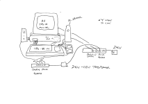
Hi. I've been trying to make a noise with my TRS-80 model 1. I have a CCR-81 tape deck with the 3 leads connected. Running a game, in this case Zaxxon, the CCR-81 led lights but no sound from the speaker or an earphone. This is when record is pressed down. I've tried with 3 connectors, no remote (the spindle then spins) and just the output. And also in the mic port. I've also tried a custom audio cable in the mic port. No sound but LED activity. Is output from the CCR-81 speaker possible?

Thanks.
 

Attachments

  • ccr-81.JPG
    ccr-81.JPG
    145.3 KB · Views: 16
You need to plug the MIC cord into an audio amp. As far as I remember, none of the cassette recorders could work as an audio amp. Like most people BITD, I bought one of the Radio Shack Archer brand amps so I could hear the audio from games. Any mono amp will work. A stereo amp can be used with a splitter. It's best if the amp has a Mic level input.
 
The cassette recorder could work but the CCR-81 mutes the signal that is being recorded. IIRC, there was a modification listed in a magazine which would have whatever was being recorded also played over the speaker. Not that I have been able to locate which magazine has it in my recent searches.

Note that playing sound over the cassette recorder requires both the play and record buttons to be pressed down and that requires reaching into the deck to depress the interlock which was normally depressed by a cassette.

Using an amp would make for a good sanity check to make sure the cassette port works correctly.
 
Plugging anything into the EARphone socket causes the internal speaker to be disconnected.

Switching the tape recorder/player into RECORD causes the audio signal to be disconnected from both the EARphone and the internal speaker.

There is a multipole switch (internal to the deck) that switches between PLAYBACK and RECORD mode. One of the poles of this switch disconnects the EARphone/speaker (S1f on page 12 of https://colorcomputerarchive.com/repo/Documents/Manuals/Hardware/CCR-81 Manual (Tandy).pdf).

S1e also disconnects the volume control - so that the signal level is automatically controlled for recording purposes (i.e. the internal amplifier is dual-role depending upon whether it is playing back or recording).

The datasheet for the IC is here: https://www.semiee.com/file/EOL2/NEC-UPC1350C.pdf.

Pin 14 is the preamplifier input. It is switched between the playback head and the input source (MIC or AUX) by S1b (and S1a).

Pin 3 is the preamplifier output.

Pin 6 is the power amplifier input.

Pin 8 is the power amplifier output. This ends up at the common (centre) pin of S1f.

My guess would be that taking a signal from across R25 (100 Ohms) with the screen of the cable connected to the 0V/GND end of R25 will give you an audio signal for an external amplifier.

Dave
 
Last edited:
You need to plug the MIC cord into an audio amp. As far as I remember, none of the cassette recorders could work as an audio amp. Like most people BITD, I bought one of the Radio Shack Archer brand amps so I could hear the audio from games. Any mono amp will work. A stereo amp can be used with a splitter. It's best if the amp has a Mic level input.
This. And the timing loops involved meant that if you were really cheap, an AM radio placed next to the computer would pick up the RFI and play the audio with a bit of noise.
 
http://www.trs-80.org/radio-shack-speaker/ mentions how to use the cassette deck as an amplifier with instructions taken from the game Cosmic Fighter. It is a bit complex. The sound from a dedicated amplifier will sound better.

This game contains programming which produces sound effects that leave the computer through the AUX plug in the cassette cable. To hear the sound follow these instructions: First, load in the game. Remove the tape from the recorder if you loaded the game from cassette. Insert the large grey plug on the cassette cable into the AUX jack on the recorder. Insert an earphone into the jack labeled EAR on the recorder. Pop open the cassette door on the top of the recorder and reach in and hold in the interlock switch that is located in the left rear corner. Now press Record & Play together and then release the interlock switch. Sound should now come through the earphone.
 
Ah yes, it depends what you actually want to do.

I assumed that you wanted to listen to what was being recorded...

If all you want to do is to listen to audio from the TRS-80 then (as stated) don't bother with the CCR-81 and just connect the audio output from the cassette port on the TRS-80 to both the CCR-81 AND an external amplifier with a 'Y' lead.

Dave
 
Of course the easy workaround here is just buy a small amplified speaker to plug the gray plug from your TRS-80 into. I’ve used a dumb LED disco ball shaped Bluetooth speaker that also has a 1/8” line input with very good results, and you can easily find something like that at the dollar store.
 
Ok Gentlemen. Thank You for explaining the potential and limitations of the CCR-81. I think my best choice would be to find a small amp/speaker device and leave the CCR-81 for data use. Thanks again. :)
 
Switching the tape recorder/player into RECORD causes the audio signal to be disconnected from both the EARphone and the internal speaker.

There is a multipole switch (internal to the deck) that switches between PLAYBACK and RECORD mode. One of the poles of this switch disconnects the EARphone/speaker (S1f on page 12 of https://colorcomputerarchive.com/repo/Documents/Manuals/Hardware/CCR-81 Manual (Tandy).pdf).

Thanks for pointing to the schematic. I doubted you until I looked at it, because I had a Model III with a CTR-80A (which was the standard Model III tape deck for the first two years of the Model III) and I used the earphone method described by Big Five. I never realized that this feature had gone away in the CCR-81.

You could buy an earphone at Radio Shack for $1.49, in contrast to $11.95 for the mini-amp. Why were I and other Big Five customers so stingy despite spending $999 to buy the TRS-80? Parents paid for the computer, kids paid for the games and sound.
 
Ah yes, it depends what you actually want to do.

I assumed that you wanted to listen to what was being recorded...

If all you want to do is to listen to audio from the TRS-80 then (as stated) don't bother with the CCR-81 and just connect the audio output from the cassette port on the TRS-80 to both the CCR-81 AND an external amplifier with a 'Y' lead.

Dave
I've bought a Loadmouse pc speaker and have connected the OUT cable to it via a lead adapter. The "Y" adapter needed to maintain the cassette function is on the way. I know the TRS-80 audio output isn't amplified but the sound is very low... and with a loud hum from the speaker when connected only. I am wondering if the hum can be reduced and the TRS-80 output increased? Someone suggested reversing the polarity of the audio jack to speaker plug. I know the audio is mono and my plugs from the OUT plug-on are stereo. Maybe a mismatch?
 
Hum is usually caused by one of two reasons:

1. Too high a gain on the amplifier and a noisy (low level) signal to start with.

2. An earth loop where multiple mains-powered devices are connected together. The screen of the cables are more likely connected to mains earth. If there is a small difference in the earth potential, this can appear as a 'signal' when amplified.

The first thing to do is to sketch out how you have currently connected things and post your sketch.

Certainly the screens/0V should be connected together.

Also, you can't (really) just connect a stereo output to a mono input (if that is what you have done). The left and right channels will interfere with each other (as they are effectively mixed together where they join). Not 100% correct in my explanation here, but it is a good enough explanation for the purpose. Think of it if one channel is outputting +100 mV and the other channel is outputting -100 mV. When you combine them, you get 0 mV. Not the intended result...

Dave
 
Hi Dave. Thanks for the info.
1. There's no gain control on the speaker/amp
2. Do ferrite clamps make any difference here?.
3. The stereo plug on the speaker is Receiving a signal not outputting one. I thought both L/R would accept the mono signal in the plug?
Also, would a mono "Y" adapter suiting the TRS-80 output and Cassette player input match up to the stereo input plug on the speaker?

Thanks
Richard.
 

Attachments

  • IMG_20230317_0002.png
    IMG_20230317_0002.png
    43 KB · Views: 20
Last edited:
Hi Richard,

Thanks for the expanded information.

1. Ok.
2. No. Ferrites would be for high frequency radio interference. If you can hear it, it is not radio frequency...
3. Stereo on the speaker is fine. Yes, one mono output can drive the stereo input ok by just wiring the left and right in parallel to the mono source.

Let me check the schematics for the TRS-80 when I get home.

Dave
 
Pin 2 of the cassette port on the TRS-80 is the 0V/GND pin with pin 5 being the cassette audio out. The pin numbering on audio DIN connectors is not necessarily 'logical', so have you checked the pin numbering with a picture on the Internet?

What type of audio connector(s) have you got on your PC speaker/amplifier, and what manufacturer, make and model is it?

Dave
The cassette port cable I have is an aftermarket job, with input and output lines clearly marked.

The PC speaker is a Diamond-Audio LoudMouse 2 with a stereo 3.5mm male jack input.
 
I assume that the 3.5 mm male is a TRS (tip, ring and sleeve) connector?

In that case, pin 5 of the cassette DIN connector (signal) should be wired to the tip and ring of the 3.5mm male connector and the DIN connector pin 2 (0V) should be wired to the sleeve of the 3.5mm male connector.

You should be able to check these out with a multimeter with the cable disconnected from everything.

Dave
Yes it is.

Yes, checked with my multimeter. It is as you've said, although unlike Ira Goldkings wiring diagram online, the data-in and data-out don't seem to have a common ground.

Richard.
 
Back
Top