Qbus
Veteran Member
How to see the hard drive in a GRiD 1520/30 series laptop:
This is how to disassemble a 1530 40 Mb HD and floppy laptop. Understand that this is what I do and may be different from the factory method and I am not considered an expert or am in any ways advising you to do it this way, this is just what I do.
First remove AC power supply from the back of the system. Then the two black feet plugs on the back of the case. Then back the two Philips screws out several turns but don’t remove them yet. With the screwdriver on the screws tap the back of the driver in to pop the front of the back cover off the display hinges and remove the screws and back cover at that time.
Second with the display unlatched but down lift the display off the hinges and flip it over to the side. Caution some displays have a power cable on the opposite side of the cable that connects it but it has a disconnect plug. You cannot disconnect the main cable to the display but you won’t need to. Remove the four screws on top of the display driver board and it will pull out with the display cable attached. There will also be a ground cable that can be disconnected but with the display card removed you have plenty of room to work just by laying it aside.
Third take a regular screwdriver and insert it between the plastic keyboard cover and the case and pop the cover out by gently prying up. That will release it from the two front latches.
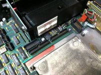
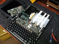
After this you will have something that looks like this.


