There seems to be an increased interest in the Grid stuff lately so I'm making an effort to post some of my findings.
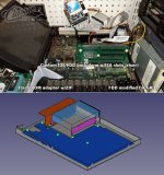
I don't know if this info is out there already but yesterday I typed up the pinouts for the 1500 series mainboard backplane connectors. The expansion bay pinouts are there too but I think official data on that has since been located. There could be errors because I did this with an meter and scope but it should be okay since back in early 2020 I made a functional homebrew replacement backplane with IDE, Floppy, and ISA slots which I ran in my 1520. It's almost a full ISA BUS except I couldn't find an inverted RESET line so I ran a wire for that. Since then I've consolidated all the logic, including the GAL, into a single CPLD chip which also generates the inverted RESET signal so the next version should be smaller and more refined. I tested with a VGA card and Soundcards (some garbage card and also a SoundBlaster Vibra 16). There are a few pictures here of my 1520 test rig. My goal is a final version that will fit inside the computer where the hard drive normally would be (and with an onboard CF-Card slot). This should work with smaller ISA cards but it will be a tight fit so I'm modeling the chassis to make sure. One of my 1520 chassis had some corrosion damage so I'm going to machine it so the CF card will be removable and ISA card connecters accessible form the side.
Basically the two 60-pin backplane connectors carry a full ISA bus minus inverted reset, floppy lines, power, and gridbits. All the IDE logic in on the backplane, decoding plus gridbits is on the backplane GAL. Gridbits is used to read the backplane ID. The BIOS then expects certain HDD and FDD combinations based on that ID. There are I think 5 or 6 different storage backplanes I've ID'd so far such as dual floppy, fdd+jvd hdd, jvd-hdd only, fdd+ide hdd, ide only, and the backplane ID also dictates which HDD's are expected as far as capacity, etc. The JVC backplanes require a daughterboard and a mainboard with the additional socket to support it.
Regarding hard drive upgrades... Unfortunately just patching fixed disk geometry isn't enough to run most modern HDD replacements such as CF Cards because the Phoenix BIOS suffers from a flaw that causes it to lock up when reading more than one sector from non-slow drives (basically anything faster than these horrible Conner drives gets unstable the faster it is). This means you can write data to such drives but can't read large files or boot from it. Fortunately that can be fixed with a BIOS patch. During patch development I tested under a custom compiled PCem emulator (modified to replicate the issue), and on real hardware including a GRiDCase 1520 (286), GRiD PalmPad 2360 (386) with a variety of CF cards and had solid success running DOS, Windows, Geos, OS/2, and disk benchmarking softwares. They all exhibited the issue before but not after the patch. I also tested with SD-Card to IDE adapters. Another person reported issues using a different storage device (DOM?) and sent me some demo code to reproduce the lockup he was experiencing but I couldn't get it to happen. So... I guess your mileage may vary. I wrote a program for patching BIOS images, RomBuster, which includes sample projects and instructions for patching the GRiDCase 1520 and 1530 BIOS's to utilize other drives (I suggest CF cards) and allows you to customize geometry. The patch source is there too so if you do have issues and identify a cause I would be interested to know.
I've got a lot of project notes on the different Grids but much of it is on paper. I'll continue trying to get it online.