• Please review our updated Terms and Rules here

[gridcase] Anyone made a pin-out sheet for the External Peripheral, and/or the P2A/P2B bus connectors behind the battery?

tschak909

Experienced Member
Joined
Mar 26, 2018
Messages
121
Location
Denton, TX USA
Just as the subject says:
The P2A/P2B connectors in the battery bay are a complete 16-bit ISA bus split into two connectors, has anyone attempted to tone out the pins and what they map to?
-Thom
 
I know they are for the ethernet cartridge, (unobtanium) but beyond that I don't know of anyone using them.
The pin outs are most likely on that pdf that you are seeking unfortunately.
 
I am aware of this. It's one of the reasons I am looking for the Technical Reference manual, as it has the pinout for these connectors, am wanting to do a version of the FujiNet that fits into the bay.

-Thom
 
Bump,
I'd also love to find the pinouts of either the Gridcase /Gridcase+ 50pin external bus connector, the 1537e expansion /HDD bay or the 15xx series expansion / battery bay pinout.
I'd love to make something similar to what I did for the Toshiba T-series (CF card + Adlib + ethernet) I've already attempted to trace out the 50 pin connector in my Gridcase Plus but gave up after a couple of hours going nowhere with the multi-layered boards. https://conventionalmemories.com/wiki_cm/3inONEder_for_Toshiba_portables
 
I'd also love to find the pinouts of either the Gridcase /Gridcase+ 50pin external bus connector ... I've already attempted to trace out the 50 pin connector in my Gridcase Plus but gave up after a couple of hours going nowhere with the multi-layered boards.
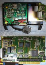
I'm not sure if this is any help or not but attached is a photo of an external 10MB hard drive that clamps to the top of my GRiDCase Plus and interfaces to the 50-pin connector. Inside is a PCB with an IDC header that appears to be an 8-bit ISA slot. There is an ISA card (Controller for the JVC hard drive) that has an ISA card edge connector but also the female IDC to match. I haven't examined it closely to determine what all the other stuff on the PCB is. Some of it is surely power related but there's logic there too. Additionally there is a pass through of the 50-pin which I would expect to be for daisy chaining except it's covered with a warning label saying not to use it.
 

Attachments

  • GridCase-50-Pin-Expansion-JVC-Hdd.jpg
    GridCase-50-Pin-Expansion-JVC-Hdd.jpg
    336.5 KB · Views: 18
It is documented in the Hardware Reference Manual, very end:
Ohh that's great, I didn't realize they were in there, guess I'll have to make a prototype adapter board then.
I'm not sure if this is any help or not but attached is a photo of an external 10MB hard drive that clamps to the top of my GRiDCase Plus and interfaces to the 50-pin connector. Inside is a PCB with an IDC header that appears to be an 8-bit ISA slot. There is an ISA card (Controller for the JVC hard drive) that has an ISA card edge connector but also the female IDC to match. I haven't examined it closely to determine what all the other stuff on the PCB is. Some of it is surely power related but there's logic there too. Additionally there is a pass through of the 50-pin which I would expect to be for daisy chaining except it's covered with a warning label saying not to use it.
Wow that's really cool. I see that the board is in labeled in French, is this from one of the SAGEM rebranded GRiDs?
Could you take a higher quality picture of the adapter board? It looks like just a bunch of logic IC's, as long as there aren't any PAL or GAL's it shouldn't be to hard to reverse engineer. Although I suppose that I'd have to get my hands on one of those to really be able to measure out everything.
 
Back
Top