• Please review our updated Terms and Rules here

Help for identify tantalum caps

zmendoza

New Member
Joined
Mar 6, 2023
Messages
5
Hello !

I want to do a full recaping of my Compaq Deskpro 286.
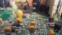
No problem to identify the big cylindrical ones but for the small tantalum i don't know ...
I managed to read these markings :

  • "686 +15K" (2 large orange caps)
  • "15-25V +M2" (5 large orange caps)
  • "104 ESM" (one small yellow)
  • "224 ESM" (4 small yellow)
  • "103" (3 small yellow)
  • "102 ESM" (2 small yellow)
  • "472 CSM" (one small yellow)
  • "473 E5M" (one small yellow)
Except for the second ref, no voltage information...
 
main-qimg-d44f957feeff88ce20b1856580c3baf4-c


Note the difference between the ceramic capacitors and the tantalums. The tants are more "spherical", while the ceramics are "flat". Ceramics don't go bad, so you won't need to mess with any of those. You'll see a lot of them used as bypass caps near ICs. The tants will tend to be at power supply rails more often than not.

This should help you figure out the number codes.
679c09306b872ea2cf53e9824ec010b0.png
 
OK... Instructive !

So :
  • "686 +15K" = 68 µF
  • "104 ESM" = 0.1 µF = 100 nF
  • "224 ESM" = 220 nF
  • "103" = 10 nF
  • "102 ESM" = 1 nF
  • "472 CSM" = 4.7 nF
  • "473 E5M" = 47 nF
But this one :
  • "15-25V +M2" ... no clue ..
And... the little ones on the front of this photo are ceramic? Not tantalum?
 

Attachments

  • IMG_20230311_190247_1.jpg
    IMG_20230311_190247_1.jpg
    213.6 KB · Views: 8
And there is no voltage mention except for one... If I choose 25V I would be safe? This is the voltage of all the electrolytic ones except the big 250V...
And what is the meaning of ESM, CSM, E5M?
 
15-25V would seem to be 15 µF at 25V. As far as working voltages, pick something that's higher than the maximum in-circuit voltage. For example, a 16V cap is fine for a 12V application.
Yes, those little caps are ceramic. I'd leave them alone--they rarely go bad. The three letters, in order, refer to temperature rating, voltage and tolerance.

Do you have any particular rationale for "shotgun" replacement of caps, particularly small ceramic ones? It's a move I'd call ill-advised.
 
I seem to remember that the three digit alphanumeric codes relate to parameters of the capacitor - as published either by the manufacturer or a Standard. Such as temperature coefficient, pitch etc.

I wouldn't bother replacing the ceramic capacitors though...

Are there any markings on the other side of the ceramic capacitors?

Dave
 
Ok! "I can see clearly now"🙂

I will change all electrolytic and tantalum caps, not the ceramic ones, as advised by wise elders. I will be a good practicing challenge for me !
 
Soldering on PCB if not done by a skilled person can cause more damage than just leaving sleeping dogs lie. Or as above, don't fix what isn't broke. Note: if you see goo oozing out of an electrolytic capacitor then that does need to be addressed. Not only replaced, but the discharge neutralized before installing the new cap. IMHO, tanalums have a way of letting you know when they want to be changed. The magic smoke comes out and sometimes flames too. If in your heart you still want to replace everything, buy a scrap board and practice. Flux, quality solder wick, good thin dia. lead-tin solder, a decent soldering iron, sharp diagonal cutters and a solder sucker plus some practice.
 
It doesn't power up. Well… on power-up : a led blinking, strange sound humming, the psu fan start (2 seconds) but only when no ISA card plugged…
The sound comes from the psu.
It's almost the same with hdd and/or floppy unit unplugged.
The psu out of the box, totally unplugged from the motherboard, there is no noise, the fan spin normally…

Some guys on Mastodon advised me to «check first if one of the tantalum caps is rotten and thus conductive.»

https://stockage.framapiaf.org/fram...356/153/613/673/original/aaa8aa9afe055110.mp4
 
Back
Top