
• Please review our updated Terms and Rules here

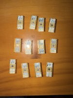
Help identifying a set of 12 Intel 1702A EPROMs with handwritten L/R labels

MrPeanut

New Member
Joined
Sep 29, 2026
Messages
3
Hi all — I recently came across a set of 12 early Intel 1702A/C1702A EPROMs ant ann estate sale and I’m hoping someone here might recognize the labeling scheme or have ideas about what system they came from.


They appear to have been kept together as a group, and several have small handwritten labels such as:


  • 29L / 29R
  • 2AL
  • 2BL
  • 2CL / 2CR
  • 2DR
  • 2FL / 2FR

There are also three chips without visible handwritten labels.


Most are white ceramic Intel 1702A devices with the quartz window and gold-colored leads/traces. Visible markings include several B7262/B6766-type markings, a couple of C1702A F1151 devices, and one uncovered chip marked 1702A S313.


I’m particularly curious about the handwritten labels. One possibility is that 29, 2A, 2B, etc. represent hexadecimal ROM pages or addresses, with L/R possibly indicating paired ROMs or two halves of a wider word, but that is only a hypothesis at this point.


I have not erased or programmed any of them, and I’d prefer to preserve the original contents if they are still readable. If this really is a matched firmware set, I’d love to figure out what machine, instrument, controller, or development system it came from.


A few questions for the group:


  1. Does anyone recognize this 29L/29R, 2AL/2BL/2CL... labeling convention?
  2. Are there known early systems that used paired 1702As in this sort of arrangement?
  3. Does the S313 marking have any particular significance beyond being an Intel spec/production marking?
  4. I’m also curious about collector value, but identifying and preserving the set is my first priority.

Thanks — I’d be very interested to hear any ideas about what these may have come from.
IMG_5940.jpeg
 
Hello,

It would help if you could do two things:
  1. Tell us what country/region were they found at. That would reduce the number of potential computers.
  2. Dump them and examine the contents in order to find any string that could give any clue.
Have a nice day!
 
Are you able to read them?

A 1702 could be Altair, SCELBI or something 8008 - but they could be anything from the early times of computing.

Dave
 
My five cents about the codes...

Last character for all codes is either 'L' or 'R'. I would be inclined to think they might be for [L]eft and [R]ight. This might indicate their position at their PCB, or even the position their module was in the overall assembly.
All codes start with what seems a two-digit hex number, which might indicate an offset or port.
Also, it seems that no code is repeated.
 
This is very helpful! I honestly have no idea how to read them, but found there are some hobbyist sources that could read them. Are these legit? Any recommendations?
 
You can read a 1702 with a simple piece of prototyping board, a simple regulated power supply unit, some LEDs, current limiting resistors and some wire links (or switches).

Each 1702 is 256 bytes, so 8 address switches and 8 LEDs should do it.

You set each address (in binary) on the switches and write down the state of the 8 LEDs. A bit of a chore - but it can be done...

Various people here (if they are local to you) should be able to read them.

There is a design on the internet fir a simple 1702 reader.

Dave
That or a microcontroller.
 
This is super helpful!! Thanks everyone. I’m in Boston MA so not sure if there are any hobbyist nearby with readers. I cal also look into doing it myself. It’s a fun puzzle
 
From the datasheet, it looks like you could make an adapter to match its pinout to a more common EPROM that can be read in a modern programmer.
 
From the datasheet, it looks like you could make an adapter to match its pinout to a more common EPROM that can be read in a modern programmer.
Not with this one!

Just to work, it requires +5V and -9V. NO GROUND.

The 1702, being the first EPROM, is not subject to the many limits posterior EPROMs are. It is really a weirdo.

P.S. "Limits" understood as "parameters".
 
>>> The L, R designations might suggest a 16-bit machine.

Possible, but extremely unlikely.

>>> Just to work, it requires +5V and -9V. NO GROUND.

The +5V and -9V are relative to something - that something being ground. Agreed, but you could feed the additional negative supply from an external battery and regulate it down to a stable -9V.

Dave
Hello Dave.

What I mean, is that the EPROM is not supplied with the ground signal.
It is actually what makes this memory extremely peculiar.
And one must supply the +5V and -9V from the same place - if they don't share the reference voltage (outside the chip) it won't work.
 
I think it could be doable with an Arduino, a prototyping shield and a SD card interface. But the power supply should be provided with 20V-24V from the shield. That would allow us to divide the voltage and distribute it to the right places. The Vin pin would prove to be very useful with this approach... Then, only the -9V regulated supply should be necessary, and could be implemented after the division with a single regulator on the prototyping board. The +5V for the logic and the +3.3V for the SD card would be provided by the microcontroller board.
 
...and the PMOS SC/MP with which I'm more familiar. No ground connection, just +5 and -7v
Since reading these 1702s is a short term or even once-only requirement, just use a PP3 battery with pos referenced to the logic and "+5 referenced" ground external to the 1702.
 
Back
Top