• Please review our updated Terms and Rules here

I wish to create a new DMA/RAM expansion card for the Tandy 1000 line.

Yeah, I'd definitely recommend the '245 for the CF card section, because that thing gets very finicky, if you saw my post a few pages back on my protoboard CF-IDE.

Speaking of Tetris, this is the PLUS version of Glitch's XT-IDE that I've been working on (I got his permission, it's open source anyways). Also adding a couple things of my own.
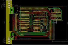
Capture2.jpg
MediaFire link here if that's too blurry

This is still a work in progress, once I can get back to it. I was doing fine tuning and confirming my measurements, but now that I know how far the transformer from the modem card goes, I'm debating whether or not to pull the first two chips on the left inwards about .200" to clear the transformer.

It is time consuming to "play Tetris" with a PCB, but very doable if you're patient.

I find that you can get quite a lot into a small space by running horizontal traces on one side of the board, and vertical traces on the other. It also assumes you're not being charged by the number of drill holes, because it involves a lot of vias.


And yes, there's two IDE headers. Same controller, but I wanted to have the option of having one end exposed to the back for an external drive, or to quickly plug in a CF card sled and transfer files to whatever is installed internally. The big exposed copper piece on the left is to be a separate piece of PCB to solder on at a right angle to form the back panel.
 
yeah just like you said it's going to take some homework how to figure out how to share the select the 245 properly .... it'll need some gates that's for sure, so it's at least two chips.

Would basically need to be something like SRAM CE or EPROM CE or CF_CS1 or CF_CS0 (to enable the 245) and IOW or MEMW for direction. (or the IOR/MEMR depending on which orientation the 245 is in.)

It turns out the equations for the PAL that controls the buffer enable and direction for the '245 that sits in front of Big Blue and all the other motherboard devices is in the manual for these systems. These seem to be the important parts:

bufenb = Imemios & romcs # memios & fdcack;
bufdir = memr & imio & !fdcack # memr & Imio & memios
# memr & !mio & ior
# mio & ior
# ior & fdcack & Imemios & Imemr;

Unfortunately I'm not particularly solid on what the syntax is for reading logic equations in this format... but I'm sure it says something about what you need to worry about when trying to share a '245 between IO and MEM devices. :p
 
it's going to take some homework how to figure out how to share the select the 245 properly .... it'll need some gates that's for sure, so it's at least two chips.

Why not just use two 245s then.. one for the CF, and one for the SRAM? I get the 245 is relatively large 74 series chip compared to some of the smaller gates, but it would certainly save the time of trying to work out the logic. I also think this may be required anyways, so that when the CF is being read.. the bus isnt trying to read erroneous data from the SRAM and vice versa.


EDIT because I didn't see it above:
(Which essentially means if you want to buffer both functions you might as well use two '245s, because the combinatory logic will probably take just as much room.)

Yea, what he said. ;)
 
Last edited:
I also think this may be required anyways, so that when the CF is being read.. the bus isnt trying to read erroneous data from the SRAM and vice versa.

The SRAM will be tri-stated when it doesn't have chip enable so it shouldn't produce any spurious data when the CF has the select if they were behind the same buffer. That said, I pretty much agree that a second '245 will probably equal about the same board space as the logic to sort out sharing one between memory and I/O.

Sharing the same '245 between the SRAM and the ROM portion of the circuit is easy, you just need to AND the respective chip selects together for CE and the same direction signal is valid for both.

That is quite true.. unless the SRAM was some off-brand chinese fake.. then who knows if they actually go into a tri-state. I also hadn't noticed that you had made the same point about taking up the same amount of space on the last page, so I edited my comment.
 
I also hadn't noticed that you had made the same point about taking up the same amount of space on the last page, so I edited my comment.

Post/Edit temporal collisions are the best.

Anyway, I'm pretty sure those Chinese chips *must* be tri-stating correctly because they worked in that PCjr. I took a peek at the jrIDE schematic and it looks to me like the data lines for all the memory devices are directly on the data lines pulled from the bus connector. If they "leaked" bad things would definitely be happening.

(YET ANOTHER EDIT) It's still my gut feeling that the reason they are not working reliably in the Tandy is more of a drive strength/noise issue than "speed", per se, but the situation is still pretty wacky, especially the part where the EX and HX behave differently. I'll do some benchmarks to make *sure* when I get my HX test mule sorted out but I don't believe the HX runs any faster than the EX.
 
Last edited:
I took a peek at the jrIDE schematic and it looks to me like the data lines for all the memory devices are directly on the data lines pulled from the bus connector.

Yeah, 6 loads is not ideal, but the JR-IDE is really the only side-car most people run and the 245 on the MB can handle that fan-out. The parts on the JR-IDE have typically less input impedance than period parts as well.

6 loads, yes a 245 was needed. But I don't understand the need for a 245 when there is only 1 downstream load like on the Plus serial and mem/dma boards. It just adds another 20+ ns of prop delay.
 
But I don't understand the need for a 245 when there is only 1 downstream load like on the Plus serial and mem/dma boards. It just adds another 20+ ns of prop delay.

I assume it's there as a "better safe than sorry" measure, which is why I decided to use it. (No implicit criticism of the jrIDE intended, BTW. It's such a compact circuit board and, as you say, it's almost certainly the only board someone's likely to bolt onto their PCjr.)

All of the the original Radio Shack boards for the EX/HX have buffers on the data lines. (The schematics for the RAM, serial, clock/mouse, and network cards are in my copy of the EX manual; I just checked and they all have them.) Radio Shack had a reputation for being notoriously stingy in cutting out "unnecessary" parts so I can't help but think they must be there for a reason. Could the weird geometry of the "tree" expansion header arrangement just be fundamentally noisy?

(Frankly I wonder why Radio Shack didn't just use a stacked PC-104 arrangement. That's basically what the PCjr's sidecars amount to.)
 
I assume it's there as a "better safe than sorry" measure, which is why I decided to use it. All of the the original Radio Shack boards for the EX/HX have buffers on the data lines.

Yeah I was referring to the OEM boards. Watching Adrian's video I noticed there was only 1 down-stream load on those boards - UART and DMA/RAM controller respectively. I thought that was weird at the time. But now I realize the 245 may be for upstream drive strength. Each add-on card also adds loading when driving back to the mainboard's 245. Another reason I'm fond of ATF150x parts for this type of work is the output drivers are beasts (44 mA source / 95 mA sink).

Frankly I wonder why Radio Shack didn't just use a stacked PC-104 arrangement.

Funny you should say that. I did notice the 104 and Plus designs have the same stacking height. I even laid-out a 4-layer Plus board with PC-104 connectors on each side of the board so a 104 board could be added in either direction. Only problem with it is the non-standard connectors and lack of a back-plate ugliness.
 
Heh. When I initially started playing with this project I was strongly considering going with using a solder-tail female connector on each board so they'd stack like Raspberry Pi shields (or PC-104 boards) and not care about being physically compatible with the original Plus layout at all. I do wish the 62 pin Plus connector itself was even remotely a standard part; not only is it an odd number of pins, it's a different height than a plain header. I still need to talk to my buddy with the 3D printer, I'm kind of envisioning going back to not caring about cross-compatibility with the original arrangement, optimizing for tight stacking, and making a backplane insert that goes in place of the original fill plates.

I'm anxiously awaiting the arrival of my ISA network card. I want to play with the spacing and see if I use a .5" spacing between the RAM board and a CF/Serial daughtercard if I'd then be able to make an ISA riser optimized to, again, stack as tightly as possible over the daughtercard and allow the ISA card's ports to be exposed with the lid closed, despite them effectively being on the wrong side of the board for the normal plus arrangement. I *think* it may actually work. Then it's time to make that fill plate...
 
I do wish the 62 pin Plus connector itself was even remotely a standard part; not only is it an odd number of pins, it's a different height than a plain header.

You can pull the plastic shell off the PLUS connector and plug a 64 pin ribbon cable straight onto it, then run that out to an ISA backplane with one of these (you get 3 for the $25): https://oshpark.com/shared_projects/cG4aZUEg I need to figure out how to build an attractive enclosure for the backplane though... I've got one that appears to be baby AT form factor, and the other has holes in weird places. But I don't need a whole AT-class case just to house a 6 slot backplane, just that little part of the case. Probably will try to cut down a cheap case sometime, but I am not sure how to make an attractive cover for it.

But yeah, I was thinking about the PC-104 style stacking thing too. I think it's a good idea. Could fasten a whole stack of boards together with standoffs threaded into each other, and then put some rubber bumpers on the bottom one (or stick them to the motherboard) to support the whole stack from the bottom. No brackets needed. If stuff could be made low-pro enough, one might fit more than 3 boards in that space.
 
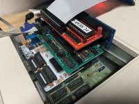
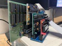
Hah, I had done something similar a few weeks ago. I trimmed down some PC/104 stackable headers and mounted them to ISA adapters.


I put in 5 ISA cards and my XT-CF-Lite.. Everything was ridiculously unstable, but it was fun to try.


In the end, I ended up with an ISA serial card, a Texelec memory card, and my PLUS-converted XT-CF-Lite in my HX, and everything works well. The fitment isnt quite perfect, but it does work.


I originally made these adapters up so that I could use a 64pin ribbon cable and test out some card designs externally from the case.
 
Last edited:
I put in 5 ISA cards and my XT-CF-Lite.. Everything was ridiculously unstable, but it was fun to try.

I wonder if it was inherent bus noise from the connectors and number of cards, a specific card, or if the PS was overtaxed?

I have run various combinations of four cards at a time; Tandy RAM expansions, VGA, XT-IDE, serial, sound blaster, network etc. and the PC has been rock steady with no problems from any combination of cards. My typical stack is the Tandy RAM, VGA, XT-IDE, and dual serial, also I have a WiFi modem and Gotek running off the internal PS and it stays within limits.

IMG_0968.jpg

IMG_0971.jpg
 
Hah, I had done something similar a few weeks ago. I trimmed down some PC/104 stackable headers and mounted them to ISA adapters.

I'm curious, Are the ISA slot connectors you have edge-on mounted on the PCBs specifically made for that orientation, or did you bend the pins on a standard PCB mount slot?
 
I wonder if it was inherent bus noise from the connectors and number of cards, a specific card, or if the PS was overtaxed?

I have run various combinations of four cards at a time; Tandy RAM expansions, VGA, XT-IDE, serial, sound blaster, network etc. and the PC has been rock steady with no problems from any combination of cards. My typical stack is the Tandy RAM, VGA, XT-IDE, and dual serial, also I have a WiFi modem and Gotek running off the internal PS and it stays within limits.
I believe I just had a resource conflict going on, but it was more just for the laugh of seeing so many cards sticking out of the machine. I only had it set up for about 10 minutes before I pared it down to the 3 card configuration I have today.


I'm curious, Are the ISA slot connectors you have edge-on mounted on the PCBs specifically made for that orientation, or did you bend the pins on a standard PCB mount slot?
They are standard slots with the pins slightly bent in. I used fairly wide contact pads on the board to allow for a good amount of solder per pin to strengthen the physical support as much as I could.
 
I wonder if it was inherent bus noise from the connectors and number of cards, a specific card, or if the PS was overtaxed?

I have run various combinations of four cards at a time; Tandy RAM expansions, VGA, XT-IDE, serial, sound blaster, network etc. and the PC has been rock steady with no problems from any combination of cards. My typical stack is the Tandy RAM, VGA, XT-IDE, and dual serial, also I have a WiFi modem and Gotek running off the internal PS and it stays within limits.

View attachment 56874

View attachment 56873

That riser card looks rather familiar. :D

I must admit that I never expected anyone to use one with an OEM RAM expansion like that. One reason I never bothered added any filter caps to the power rails was that most of the modern cards have their own - it's good to see that your setup is stable. :cool:
 
Back
Top