• Please review our updated Terms and Rules here

IBM 5150 - MDA - Parallel port Error 432

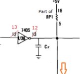
where is resistor 1P1 ? is it part of the resistor pack RP1 ? on the resistor pack between pins 5 to 16 are 1ohm resistance.
 
where is resistor 1P1 ? is it part of the resistor pack RP1 ?
Yes, part of RP1 - The 'R' was accidentally cut off in my diagram.

on the resistor pack between pins 5 to 16 are 1ohm resistance.
Of course, you are measuring multiple parts in parallel, and so RP1 isn't necessarily at fault. I've encountered resistors in resistor packs go open, but have yet to encounter one go short.

( And you have the loopback plug removed, eliminating a problem source related to the BUSY line. )
 
Yes, loopback plug is removed. The card in on the bench. And I’m reading the basics of how the parallel port works.
By the way my card is the early version (green pcb) looks identical to the card here Early mda
 
By the way my card is the early version (green pcb) looks identical to the card here Early mda
That photo is of the actual one sitting in front of me right now.

on the resistor pack between pins 5 to 16 are 1ohm resistance.
Those measurement points are the same as measuring between pins 12 and 14 (Vcc) of U38. My measurement between those two pins is about 4K ohm. As I expected, if I measure between pins 5 and 16 (Vcc) of RP1, I see the same value.

You are measuring 1 ohm. So, referring to the diagram at [here], the possibilities as I see them are:
- Faulty RP1
- Faulty U38 (internally, pin 12 shorted to +5V)
- Faulty U37 (internally, pin 17 shorted to +5V)
- Faulty PCB
 
measuring the resistances the U38 pin 12 to 14 is slightly lower than on U37, or RP1.
and I actually have a 74LS05 to hand.
so I'm going to try desoldering that chip first.

edit - its not the U38 74LS05 chip ! that is out of the board. next out comes the U37, 74LS240 chip....
 
Last edited:
and the 74LS240 also out of the board - but the short is still on the board !
74LS05 and 74LS240 chip test as ok on my Chip tester/rom burner.
so next the Resistor Pack ...
 
Sometimes IBM omit capacitors on their circuit diagrams, and just in case, on my card, I followed the trace about the card, and didn't find a 'non-disclosed' capacitor on the trace.

It seems very unlikely that the short is in the DB25 connector (+5V goes to none of its pins).

You may need to start breaking the trace into segments to work out where the short is. And then bypass the short.

Are you really really sure about the 1 ohm? I don't mean to be insulting, but you will be kicking yourself later if this is a measurement problem.
 
None taken, Im going to check everything again tomorrow and think about how to proceede.

($50 for another one on ebay, but thats a defeatist attitude).
 
@ modem7 can you have a look at chip U101 (74ls74) is pin 14 vcc connected to pin 4?
6E75F72E-7FBF-49A0-91C5-49E908882308.png
Pin 4 is on the 5V, again 1ohm between pin 4 and 14.
 
Last edited:
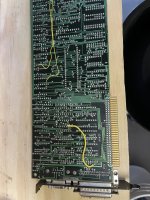
I put another cut on the backside of the board where there is a long straight run top to bottom, this isolates the short between these two cuts.

I’m going to take U40 and U41 off the board and look underneath. I’ve gone this far and I need practice with my desoldering iron.

One remaining question is where is capacitor Cx ?20027189-BAAF-4779-A080-1C60E3E7F1E8.jpeg
 
All is good ! A nice new bodge wire, yellow for consistency. A bit thicker.C2D3A135-5D67-468D-9F95-6E5DE38AC236.jpeg
32A59703-FADA-49A7-A448-120849CF388E.jpeg
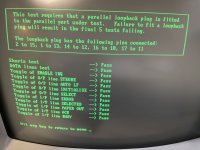
And all is good again.
I never did find the fault under the IC’s , possibly just some flux or solder flash, or something inside the board layers…

Once again thank you modem7 for walking me through the troubleshooting process.
 
Back
Top