• Please review our updated Terms and Rules here

IBM 5151 MDA monitor fixing

soviet9922

Veteran Member
Joined
Jun 12, 2013
Messages
555
Location
Montevideo, Uruguay
Hi got an IBM 5151 monitor, and it has seen better days, the "seller" told me that someone dropped it from a truck when he moved places in the past.
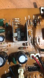
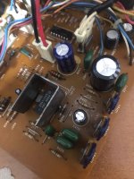
The casing is cracked but the guts of the monitor are ok the PCB is in a single piece with no cracks don't seem to be any cold solder joints.
Checked all connectors unplugged and plugged them cleaned all the pots and the board.

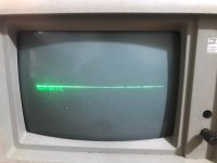
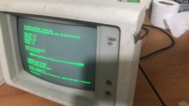
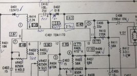
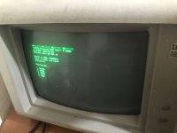
Now the monitor powers on ok but is vertically collapsed I can see all the images compressed in a single line but the last text line from dos shows up fine:
The adjustments don't seem to change this.

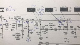
Maybe someone that is familiar with these monitors could help, need some ideas about where to start to look at them.
 

Attachments

  • 18be31f4-57cb-4625-894c-0ce2d31ddf90.jpg
    18be31f4-57cb-4625-894c-0ce2d31ddf90.jpg
    92.1 KB · Views: 17
I'm pretty sure that you will have a multimeter, but do you have an oscilloscope?

A circuit diagram of the vertical deflection section is at [here]. An alternate version is at [here]. As you can see, there is not much circuitry. And heed the warning shown on those diagrams.

Per the diagrams, is the expected DC voltage (approx. 15V) reaching the TDA1170S chip ?
Thanks for the diagram, checked and the tda1170s is getting 14.8v in PIN2.
Pin 9 gives stable 49.8hz C401 has also stable 49.8hz at the pc connector side, but the other side of the cap that goes to pin 8 of the TDA1170 is jumpy and can see 49.8hz but it jumps on the scope to 16hz, and **.
Maybe the cap is bad? not sure if this is normal.

here is a video:
 
Thanks for the diagram, checked and the tda1170s is getting 14.8v in PIN2.
Per [here], check pin 5 as well, expecting a slightly lower voltage. (The TDA1170 datasheet indicates that pin 5 is a 'supply' pin as well.)

C401 has also stable 49.8hz at the pc connector side, but the other side of the cap that goes to pin 8 of the TDA1170 is jumpy and can see 49.8hz but it jumps on the scope to 16hz, and **.
Maybe the cap is bad? not sure if this is normal.
Based on what I see on my 5151, it is normal.

C401 and R401 form a differentiator. At the junction, you end up with what is shown at [here], a negative 'spike' for the negative going edge of the sync pulse, and a positive 'spike' for the positive going edge of the sync pulse. The amplitude varies a lot from pulse to pulse.
Of that, diode D401 passes only the negative spike. The waveform on the anode of D401 is [here]. If I expand the timebase, I see what is shown at [here].

The waveform on pin 8 of the TDA1170 in my 5151 is shown at [here].

Pin 9 gives stable 49.8hz
That is a good sign that the TDA1170 is syncing to the MDA sync pulses. Why?

From a TDA1170 data sheet: "The vertical oscillator is directly synchronized by the sync pulses (positive or negative); therefore its free running frequency must be lower than the sync frequency."

With no sync in, the TDA1170 circuit in my 5151 free-runs at about 45 Hz; I see the expected waveforms on the various TDA1170 pins (excepting of course, pin 8), except that the frequency of the waveforms is about 45 Hz. As soon as I then plug my 5151 into an operating MDA card, the frequency of those waveforms changes to about 50 Hz.

Do you see the same behaviour when monitoring pin 9 ?

BTW. At [here] is pin 9 of the TDA1170 in my 5151. And at [here] is pin 4 (the output).
 
Further to my previous post:

I measured the DC resistance of the vertical deflection coils and R413 combination (3 things in parallel) and discovered an amount of about 4 ohms.
Can be measured in-circuit because of capacitor C408.

View attachment 1253424
Got 5.6 ohm there.
To so much time because I ordered a new vertical chip TDA1170 and like to replace it first.
Now have installed the new IC.
But the issue continues the same, seems like the old chip was ok.
So the issue must be elsewhere.
 

Attachments

  • 6ee9a281-39e8-4fda-be41-50f2e5a6249e.jpg
    6ee9a281-39e8-4fda-be41-50f2e5a6249e.jpg
    258 KB · Views: 2
also, i got another 5151 monitors from a friend as a loan and installed the board from his monitor into my mine (reused the "bad" monitor tube/yoke PSU and wiring).
And the vertical deflection works so now i'm 100% sure that the monitor vertical and horizontal deflection coils are OK.

This picture is using my friend's monitor board:
 

Attachments

  • 26257dc4-7f16-430c-a8f8-192e3dd4cc8a.jpg
    26257dc4-7f16-430c-a8f8-192e3dd4cc8a.jpg
    279.9 KB · Views: 7
Checked most of the components on the vert section, and all seem OK replaced a couple of electrolytic because they were a little out of spec.

So check all the voltages and waveforms according to the shematics and sam's computer facts pdf and the thing that shows up the most for me is that:
At D402 they are 14v on its anode side like in the schematic but pin 5 (that is connected directly to the cathode side) has only 6v peak and on the schematic, it shows 13.68v.
The cap C410 is in parallel there and is ok replaced it with a new part anyway but seems to me the diode is creating a massive drop in voltage to half of what shows in the schematic is this possible?
 

Attachments

  • 1101c4ad-b622-48f0-830b-71dca5938683.jpg
    1101c4ad-b622-48f0-830b-71dca5938683.jpg
    298.7 KB · Views: 1
  • d80ce232-768e-422c-9612-9adc1c730e27.jpg
    d80ce232-768e-422c-9612-9adc1c730e27.jpg
    304.4 KB · Views: 1
So it was D402, and the diode was bad!, replaced it for an IN4007, and bang! the monitor works again.:love::love:
This is super bizarre for me because the diode passes all tests in my component tester I tested it at the beginning of this also using the old tester diode mode method and it look ok but it is bad it eats half of the current and drops the voltage to half!.


Now only have to work on fixing the case of this monitor because it looks like it was dropped from the back of a truck.
 

Attachments

  • 275d8ee5-cde4-4590-ab49-e5d958d28391.jpg
    275d8ee5-cde4-4590-ab49-e5d958d28391.jpg
    228.5 KB · Views: 10
  • 04c5087d-1a96-470c-876b-2547cec3183b.jpg
    04c5087d-1a96-470c-876b-2547cec3183b.jpg
    298 KB · Views: 10
Now only have to work on fixing the case of this monitor because it looks like it was dropped from the back of a truck.

I used JB Weld (epoxy) and auto body filler to repair my Mitsubishi VGA monitor bezel, which was quite badly damaged.
I removed the CRT from the bezel and used JB Weld to reinforce cracked areas, and auto body filler to fill in missing
plastic. Some sanding of the body filler was required......and still need to find some paint that matches.
 
This is super bizarre for me because the diode passes all tests in my component tester I tested it at the beginning of this also using the old tester diode mode method and it look ok but it is bad it eats half of the current and drops the voltage to half!.
I remember that, donkeys years ago, I was tasked with fixing a DEC LA120, that at power-on, would fast-slam its carriage hard up against the right limit. It took me a long time to track down the cause to a diode, a diode that showed as okay using the diode test of a multimeter. We worked out that the diode was 'leaky'.
 
Back
Top