• Please review our updated Terms and Rules here

Interest in I4004

I was looking at the memory usage of the Maneuver board program. I believe if you only enter one target ship one can run it on just two 4002-1's, rather than the full complement of 5ea 4002-1's and 4ea 4002-2's that would allow 10 target ships.
If anyone is interested, I have it posted on GitHub.
Slob would need to modify the display to handle the non-7segment displays. That wouldn't be too much work though.
It would be more work translating my assembly code to work with a different assembler. It is almost 4K of code. You might need to make some hardware to deal with the 25 switch keyboard but I'd think some arduino work and a couple more LS244s would be enough to deal with a fake keyboard from a PC on serial or usb.
My PC board is coming along. I'm fighting the frustrating KiCad footprint library. The footprints they have are never exactly what I want it is is an uphill battle to get the footprint I want to select. It is confusing. I wanted to use different IC boarders and such but it seems to fight my all the way. The 7seg displays have only 12 pins instead of 14. I made the display schematic piece from a 14 pin part but left those pins there. The footprint I made was missing 2 pins and the tool wouldn't let me use the 12 pin one with the 14 pin schematic, even though I made the pins as no connects. It was frustrating. I needed to go back and fix my schematic element to remove the pins that were not there.
As I said, things are coming along, just a little slow. It prints out a pile of error since my switch are treated a passives and a bunch of input have no source. I don't know if I'll just leave it that way and ignore the errors.
Dwight
 
Last edited:
Tools for 4004 Development

Tools for 4004 Development

2716/08 "Promulator"

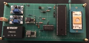
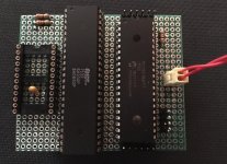
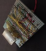
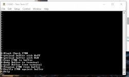
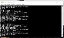
As I had mentioned, in order to develop the 4004/4040 boards I needed a "promulator" so that I wouldn't have to constantly "burn and learn" with UVEPROMS. Even the tedium of installing/removing a 28C16 EEPROM would be a PITA. So, here is my design, using a PIC 16F18877 40-pin DIP, and a IDT7132SA100P 2kx8 dual port RAM. I used this particular PIC because it has lots of ports, RAM, flash for code, is a DIP, and is fairly cheap to buy, use, and to program (no crystal is really needed). Communications are handled serially at 9600 via a USB serial adapter. Pictures and acreen shot of the menu is attached. I THINK that this will work with 2708's or '16's. Note that there is an external +5 power supply. You MIGHT be able to get away with having the target board power it but I didn't want to take that chance.

A much better programmer than I am could, I believe, substitute hardware for software here with basically no loss of functionality. This is a pretty fast chip (32 Mhz), and it might be possible to write interrupt-driven change of pins or change of CE/read code to present new data given the address, therefore, you wouldn't really need the dual-port RAM (somewhat rare, expensive, and no longer made) at all. The older UVEPROM chips had an access time of about 500 nsec; this is enough time for interupt overhead and a little code at a 32mhz clock. You might have to patch in some assembly to pull this off.

As it is, this is a two-chip design; but it would be pretty cool to get it down to one!

The code was in "free" version Microchip C with MPLAB X as the environment. A Pickit 3 was used for programming and debugging. I was not very happy with the action of the debugger but at this price who can complain. I'm thinking about getting an ICD3 which is on sale for a few more days now that the ICD4 is out. THAT is a much better debugger, and although I stink at C coding, I am a very determined debugger and can basically make anything work if I can debug it.

2708 (04?) Programmer

Although I've already built my 4040/4004 boards around 2716's, they REALLY would have been more period-accurate with 2708's. I had some 2708's, but no programmer for them. With code and I/O very similar to the promulator, I modified that using "control-c control-u" object oriented programming into a 2708 programmer, also shown. It seems to work fine. You may laugh at the power supply design, a USB wall wart going into FIVE (count them, five) DC-DC converters. Why?

One is for the +25 programming pulse for the 2708
One is for the +12 supply to the 2708
The +12 goes through another DC-DC converter to get down to +5 for the 2708,PIC, and 7407. USB power supplies can be a little off on the voltage and noisy, so I chose this route.
An isolated DC-DC converter (meant for Ethernet boards?) produces -9, which I bring down to -5 through ANOTHER DC-DC converter for the 2708.

I don't think that I paid more than 75 cents each for any of these items, and it was expedient. The regulation of the Chinese boards at "rated" loads is questionable according to others due to barely-adequate coils and capacitors. I might have been able to do without one of them but I didn't want to press it.

This will probably be "it" for the 4004/4040 project until the fall/winter.

i3.jpgi1.jpgi4.jpgix1.jpgix2.jpg
 
Hi Jim
I've noticed that you've use a 100 ohm resistor on the VDD lead or the 4201. I'd not seen this on the Intel sheets but I've seen it a couple of times now. What is the purpose?
Dwight
 
The resistor is on the "Clock Generator Implementation" figure in the 4201A Data Sheet. Intel refers to it as a current limiting resistor. I didn't want to tempt fate by not using it.
 
The resistor is on the "Clock Generator Implementation" figure in the 4201A Data Sheet. Intel refers to it as a current limiting resistor. I didn't want to tempt fate by not using it.

I basically copied what you did; after looking at this on an oscilloscope, I think that it rounds off the square wave from the oscillator (less harmonics, ringing?). The need for the resistor is apparently load-dependent (i.e., how many chips you hang on the output).
 
I'd seen resistors on the clock lines and assumed these were to deal with rise time issues. I'm in the process of laying out my board. I guess it wouldn't be too bad an issue to add a location for a resistor. I do already have resistors on the clock signals. I have 9 ea 4002s so I have quite a bit of load. I expect I may have to adjust the clocks for enough rise time. The PMOS in general don't have hard pull down to VDD but the clock generator has to have hard VDD. I suspect that they my have some overlap of the pull up and pull down outputs transistors. This may be there to deal with cross over issues. None of my data sheet show the resistor but I guess it is best if I add it as well. This is my first time using the 4201. I have a SIM4-01 board but it uses a discrete transistor clock driver.
My board is large. It is now 5X8 inches. I expect to use OSH Park. They are not the cheapest but then they are not the Cheapest either. I've had good results from them in the past.
Thanks
Dwight
 
Oh Jim
I was looking at the code snippets you have on your web page. The maneuver board code has quite a few good snippets of code. There are things like decimal multiply, divide and others. Of course it has the codic code for sines and cosines but that is a little heavy for general 4004. It makes use of quite a few of the useful snippets. The divide routine was originally written by Gary Kildall! I believe I've posted where you can see the original code. I have it in my assemblers syntax but that might be harder to transfer except to use to verify some of the bad print in the original PDF. I also have a HEX code on github that could be used to compare to. You'd just assemble at a matching address and compare the results. The code works on 16 decimal digits ( one register of RAM memory ) at a time.
Dwight
 
Github has changes something in the URLs that used to work but have changed.
My code is at:

https://github.com/prog4004/I4004-projects/tree/master/maneuver

There is a string to search for to find the original pdf in the read.me. If you are interested there is one other I4004 project in the NPS library. Do a search for Kildall and you should find it. It is for calculating the maximum weight to take off with a helicopter. All the reset of the stiff looks to be 8008 and 8080 stiff. Kildall had a lot of ties with Intel.
Dwight
 
Dwight,
I finally got around to massaging the "maneuver.f" file found on your GitHub page so that it assembles with the assembler I use (Alfred Arnold's Macro Assembler AS). The resulting binary matches "maneuver.bbn". Now to see if I can figure out how to use the decimal arithmetic routines.
 
I've been writing a code source code format translator to do what you've done for another friend.
For the most part, the BCD data is put into a block of RAM, with pointers in some of the registers for the ins and outs. I forget how sign is handled. I know for some of the addition related to the corrections, he uses 9's complement math for subtraction of constants.
The math routines were written by Gary Kildall ( at least that is from the notes ). That part is a little confusing because in the original listing, he used symbolic names for the registers ( most likely Kildall's original names ) but in has code, he passed thing to the routines by register number.
I'll look in my notes and see if I can find the notes I made about the input and output pointers used by the math parts. You'll likely want to copy out the move routine that moves data from one RAM block to another, as well.
Dwight
 
I believe ( but could be wrong )that multiply and divide were unsigned. You'd need to handle the signs separately.
The CODIC routine works on a 45 degree maximum angle. Angles are translated by rotating in 90 degrees increments and/or flipping until they are in a 0 to 45 degree range. The sine and cosine are then calculated with the CORDIC based on the these translated X and Y. The translation is kept track of so that they can be translated back into the proper quadrant and sine/cosine swap. The flipping of angles in the 45 to 90 degree range keeps from having really large numbers in the value of the tangent. This flip can be undone by exchanging the sine and cosine results. The quadrant is corrected by the proper +/- sign attached to these calculated values.
The math is done on 16 digits. You'll note that the constants are 18 digits. I believe the extra two digits are either sign or shift bits ( ?? I don't recall ) to be kept in the RAMs character nibles. Although, the calculations are done on 16 digits, the CODIC only does enough steps to get 3 decimal digits of angle. If you wanted more you'd need to do more extended steps.
I've notice some errors when working with angles of exactly 0 degrees. In these cases, I cheat a little and do angles of 0.1 degrees and 359.9 degrees. The results are better. I think there is some errors in the best flips and rotates when getting to 0 to 45??
Dwight
 
I believe both the multiple and divide routines were written by Gary Kildall. You might mention that in you github. It might catch more people looking up Gary's history.
What is the issue with divide? I may be able to figure it out. I have notes someplace as to the input and output pointers.
Dwight
 
My maneuver board is making slow progress. I have a few more parts to install but my wife has voluntold me into several projects.
I hope to find time soon and see if the board works. I may have to beef up the power and grounds a little as these are currently connected with small traces. The board was intended to be 4 layer but as a prototype it needs to be cheap.
 
The multiply routine uses pointers to three registers. It was easy enough to load up the registers with test values, run the code in an emulator, look at the results and figure out what was input and what was output. The divide routine uses four pointers and when I run the code in an emulator, the results don't seem to make any sense.
 
You also need to look at the sign flag bits with the RD0 and WR0. You should enter from the DVRT rather than directly into DECDEV. DVRT makes both values positive so the divide routine doesn't get mixed up. I think it does the divide with the decimal point in the middle of the 10 digit number. In other words 0000400000 is 4.0 . I think that makes a difference when doing divide. R2 (A) and R6 (C) are the pointers to the inputs. I'm not sure what divides what. I believe R8 (Q) points to the answer and R4 (R) points to the remainder.
Dwight
 
Last edited:
Got it mostly figured out. P1 (R2,R3) points to the dividend. P3 (R6,R7) points to the divisor. P4 (R8,R9) points to the quotient.

I don't know what P2 (R4,R5) points to, but it's not the remainder. for example, when I divide 9999999 by 2, the register that P2 points to contains all zeros. When I divide 1000 by 3, the register that P2 points to contains 1000. When I divide 22 by 7, the register that P2 points to contains 600000. ???

The quotient is a 16 digit number with the decimal point in the middle. For example, dividing 9999999 by 2 gives 4999999500000000 which is 4999999.500000000

More about P2:

When 1000000 is divided by 3, P2 points to 1
When 100000 is divided by 3, P2 points to 10
When 10000 is divided by 3, P2 points to 100
When 1000 is divided by 3, P2 points to 1000
When 100 is divided by 3, P2 points to 10000
When 10 is divided by 3, P2 points to 100000
When 1 is divided by 3, P2 points to 1000000
 
Last edited:
Back
Top