• Please review our updated Terms and Rules here

Is this problem "CRT breathing", or something else?

inv

Member
Joined
Feb 26, 2023
Messages
28
I got a 14-inch Sony Trinitron RGB monitor, CPS-14F1, which was probably sold only in Japan in the 80s-90s. Mine is made in 1991.

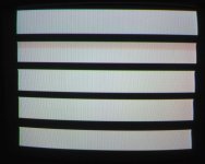
It shows an "interesting" problem when a pattern consisting of rectangles is displayed as follows. The upper left corners of the white rectangles on a black background are hooked toward the left, while the upper right corners are hooked to the right. This happens when the white rectangles are wide. It is more significant when the brightness and contrast are high (when the RGB drive level is high).

1685627477228.png

1685627660517.png


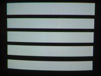
When the screen image is inverted, the hook direction is reversed, as shown below.


1685627394985.png


By googling, I learned about "CRT breathing." The symptom of this monitor seems similar to the description, but I've never seen what "breathing" is in my eyes, so I wonder whether this is actually the case.

One thing I am particularly not sure about is the following.

If I understood breathing correctly, breathing typically happens when the cathode ray current is high (i.e. the pixels are bright). In this case, higher current the anode current of the tube is increased, so the anode high voltage drops. This lowers the speed of the cathode ray so that it is more easily deflected by the same magnetic field of the yoke.

Perhaps this could explain why the upper *left* corner of the white rectangle (in the first photos above) is stretched left. But, if this explanation was correct, the upper *right* corner of the same white rectangle should have been stretched toward the right, because the beam would be deflected further to the right. Actually, the upper right corner is stretched toward the left, as shown in the first photo.

So, I wonder if it could be some side effect changing the horizontal deflection pulse timing (caused by high load on the HV side of the flyback, due to the high current cathode ray), rather than "CRT breathing."

As aforementioned, I observed that this issue is less significant when the RGB drive level is lower. So, I tried to reduce the distortion by lowering the RGB level but raising the screen (G2) voltage level. It is partially helpful, but it doesn't solve the problem, because the black level becomes excessively bright.

Any comments will be greatly appreciated!
 
If you could post the schematic of this monitor I could probably offer up some suggestions of the possible causes.

Also, where is your signal source originating from ?

Do you have a scope ?

Is this a pure RGB drive (where sync is derived from the G signal), or is it a system of separate syncs to the RGB as in a 5 cable RGBHV connection ?

What you are looking at though is a phase error, where the video information (and sync derived from G or not) is causing a transient in the sets H AFC circuit and it is taking about 7 to 9 scan lines time to correct. And it is signal amplitude dependent.

Nothing to do with CRT breathing.
 
Last edited:
You might be expecting too much from this monitor, which appears to be a TV with no tuner, rather than a purpose built computer monitor. A computer monitor tends to have better voltage regulation than a TV. CRTs often show various non-ideal artifacts when asked to display certain test patterns. How does it look with normal content at reasonable brightness and contrast?
 
If you looked at the H.AFC control voltage (the variable DC voltage which controls the frequency of the H scan oscillator) with the scope, likely you would see a glitch in it corresponding to the the twist at the top of the blocks where the video is white or black, with two polarities, so it causes, in this case, when the white block appears the video to arrive early wrt the scan and late for the black block.

Essentially you are seeing a PLL system correct a sudden phase error and the TV is acting in a way like a scope, enabling you to see it.

One handy thing about TV repairs, the image, if there is one, has features which can help the diagnosis.

Generally the video information and the sync should be completely independent. With a composite signal they interact at the sync separator, producing effects like this. With an RGB system where sync is encoded in the G signal they can interact with the G level (the level can affect the sync extraction and phase) but in a system of RGB with separate H & V syncs, the video content & sync should be completely independent and the video content of the RGB channels have no effect on the syncs, especially the phase of the H sync.

Unless say there was some interaction that should not be there; such as CRT beam current or video output amplifier currents putting ripple onto the power supply and that dynamically altering the supply that is powering the H.AFC circuit, that would be an easy fix. The inputs to the AFC circuit are the sync on the one hand, and often a pulse taken from the H scan output stage and it is possible to have a problem with that feedback too. In any case, one good diagnostic test to examine any interactions between the video content and the sync, is to simply disconnect the sync feed into the H sync processor IC (or disconnect the H sync if its a separate feed) and adjust the H hold control until the picture floats by horizontally and check if the white & black blocks are reproduced without the error, which they probably would be if the source signal is normal.

One reason can relate to defects in the source signal that the sync is extracted from, which is why I asked about the source and type of the RGB signal and may or may not arise in the set. In any case it looks fixable but the cause would need to be found.
 
You might be expecting too much from this monitor, which appears to be a TV with no tuner, rather than a purpose built computer monitor. A computer monitor tends to have better voltage regulation than a TV. CRTs often show various non-ideal artifacts when asked to display certain test patterns. How does it look with normal content at reasonable brightness and contrast?
Probably that could be right. The monitor shows great images when the content is "normal" if the screen and RGB drive level are adjusted appropriately.

On the other hand, perhaps I am just having fun thinking about how one could improve it, even though it might not be a reasonable thing when one considers the time-outcome ratio ^^;;
 
If you could post the schematic of this monitor I could probably offer up some suggestions of the possible causes.

Also, where is your signal source originating from ?

Do you have a scope ?

Is this a pure RGB drive (where sync is derived from the G signal), or is it a system of separate syncs to the RGB as in a 5 cable RGBHV connection ?

What you are looking at though is a phase error, where the video information (and sync derived from G or not) is causing a transient in the sets H AFC circuit and it is taking about 7 to 9 scan lines time to correct. And it is signal amplitude dependent.

Nothing to do with CRT breathing.

Thanks a lot for the very interesting comments. I am glad to learn that it is not CRT breathing, as suspected.

The signal source I use is RGB + separated CSYNC, generated by an 8-bit computer.

One thing I have to check about the computer hardware, regarding your detailed comments, is whether the (separated) CSYNC signal is indeed the Y signal of the S-video output. In fact, the computer is homemade by myself, and it has a switch selecting CSYNC (to monitor) from either Y or pure sync (75-ohm, produced from a TTL signal). I am not sure which side the switch was when I was doing the test. Unfortunately, I've been out of town and will be for another week, so I can't confirm it until then. I will check it when I am back.

I have a scope. There is no available schematic diagrams of this monitor. So, I am considering drawing schematics from scratch. When I have some progress, especially for parts that seem relevant to the comments, I will post an update.
 
Since the distortion is reduced when the contrast is turned down, it can't be a sync issue. Power supply regulation would be the area that needs improvement.

The best monitors use direct feedback to regulate the high voltage to the CRT. There's a voltage divider to measure the actual anode voltage and keep it well regulated. Most TVs and cheaper monitors just regulate the B+ supply to the horizontal scan circuit, and hope for the best. Tired capacitors in the low voltage power supply could make regulation under load worse.
 
Since the distortion is reduced when the contrast is turned down, it can't be a sync issue. Power supply regulation would be the area that needs improvement.
Probably right, but it could depend where the sync was extracted from. Possibly not in this case, but if it was extracted from the G signal, post contrast control, then the contrast could indeed affect it.

Notice how the defect extends over a number of scan lines that you can count on your hand.

Generally the EHT (final anode voltage) cannot act that fast due to charge storage. The H scan output stage could, with lousy filtering on the B+, but, not likely to produce that rapid skew.

My money is on a sync phase shift somehow affected from the picture(video) content. But I have to confess, with the limited information presented on the thread, I cannot figure out how.

I'm back home and did a quick test to check the sync signal of the computer driving the monitor. I tried both the (S-Video) Y signal and a pure CSYNC signal as the sync input to the monitor (the monitor has a SCART connector, accepting RGB+CSYNC), and confirmed that the results were identical. That is, the same problem was observed in both cases. So, perhaps it's not an issue of the sync separation.

Just in case, I added a 330uF filtering cap to the B+ voltage output of the power supply, hoping it may help the B+ voltage regulation, but no change was observed.

Although I have no background on the H AFC at all, I'm interested (very much!) in the possibility of the H sync phase shift. I'm trying to learn more about this, mainly by googling. So, any comments will be greatly appreciated.

Because no schematic diagram is available, I started to draw it from scratch (but still very far from completed). I traced the horizontal scan circuit a bit, and found that the horizontal pulse is generated by Sony's CXA1021AS, as shown in the following partial diagram. Here Q502 is the horizontal output transistor.

1687166787486.png

I guess this IC (CXA1021) contains the H AFC circuit as well, but unfortunately, there is no information on this IC on the net at all --- I could find no datasheet, and no other monitors using this IC. I wish I could find a datasheet providing some information about a feedback circuit (from horizontal output to H AFC). Perhaps I should dig further into the circuit...
 
I still say you're just asking too much from that monitor. The alternating black and white stripes mean that the HV supply is going from full load to no load and back again suddenly. The power supply and HV regulation and filtering just aren't good enough to handle that without artifacts. The HV and horizontal scan are part of the same circuit, so it's not a surprise that sudden load changes on the HV will also affect the horizontal scan.

I took a few pictures of a similar age Sony TV I happen to have, and the results are similar. One image it at high contrast, and the other is with the picture dimmed to show that the geometry is good. Due to the camera's auto exposure, they look the same brightness, but bright.jpg is much brighter than dim.jpg. With normal picture content the TV shows a good image.
 

Attachments

  • bright.jpg
    bright.jpg
    182.9 KB · Views: 3
  • dim.jpg
    dim.jpg
    212.8 KB · Views: 3
Back
Top