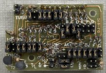
Hey there. I have a M396F 386 SX 33 board in a case and am having trouble getting the turbo LED and display to work correctly. None of the diagrams on Minus Zero degrees match mine.
Here’s the first problem:
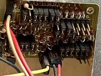
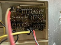
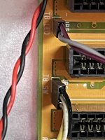
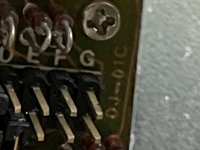
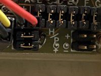
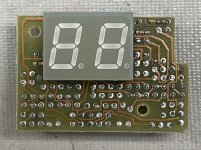
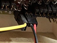
As hooked up, the LED display shows a 16 when turbo is pressed and the Turbo light is on. But the PC operates at the slow speed as noted by the memory clicks. When I unpress the Turbo button, the LED display shows 06 and the turbo light is off, and the computer runs in fast mode. The three pin is connected to white/black on the two pin connector here in this instance.
I switch the three pin Turbo switch to the other two pins which are yellow/white. All it does is reverse the above. When pressed, the turbo light is off and it says 06 and it runs fast. When unpressed, it says 16, the Turbo light is on and it runs slow.
I think the board is showing the right stuff in the first instance, but the computer is the wrong speed.
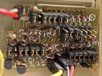
Secondly, does anyone have a instruction set to show how you change the display with these jumpers?
Thanks!
Here’s the first problem:
As hooked up, the LED display shows a 16 when turbo is pressed and the Turbo light is on. But the PC operates at the slow speed as noted by the memory clicks. When I unpress the Turbo button, the LED display shows 06 and the turbo light is off, and the computer runs in fast mode. The three pin is connected to white/black on the two pin connector here in this instance.
I switch the three pin Turbo switch to the other two pins which are yellow/white. All it does is reverse the above. When pressed, the turbo light is off and it says 06 and it runs fast. When unpressed, it says 16, the Turbo light is on and it runs slow.
I think the board is showing the right stuff in the first instance, but the computer is the wrong speed.
Secondly, does anyone have a instruction set to show how you change the display with these jumpers?
Thanks!
Attachments
-
 09B1CE02-E665-4C61-86EF-25373EBA96EA.jpeg1.7 MB · Views: 22
 -
 65A69EAB-96EF-42B4-BF77-A97C1B4628E1.jpeg1.3 MB · Views: 18
 -
 9544D539-09CB-42A9-B680-FDE7A32EA4D1.jpeg803.3 KB · Views: 17
 -
 D0AF37B3-EBC6-4067-85C3-7E4C4216515C.jpeg1.2 MB · Views: 13
 -
 CC0E67CC-D300-4F36-AB20-7D70BBDF3EA0.jpeg589.1 KB · Views: 12
 -
 EEF92022-F498-4A53-8E95-80D274D18CE2.jpeg630.2 KB · Views: 17
")