• Please review our updated Terms and Rules here

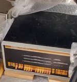
ITT Satellite navigation system 6000 (PDP8/L)

I wrote a paper comparing all of the 8 CPU's a while back. The note says 2010 but I started working on it in the 90's. I'll attach it here. Let me know if you see any mistakes.

Hello Doug. Thanks, that is a very nice overview.

Well done Roland, you got it going so fast! There are special set of maindecs specified for testing the 8/I and 8/L CPU, use them!
http://www.bitsavers.org/pdf/dec/pdp8/pdp8l/DEC-8L-HR1B-D_8LmaintVol1.pdf se section 5.2 page 68 in the PDF.
Otherwise, try CHECKMO - a chess program. You can let it play against itself and will keep itself busy for a very long time.

Thanks, I found this paper tape list at the site of Philipp Hachtmann.
It seems many of them are mentioned in the list you mentioned.


In the meanwhile I found out why that little program failed to test the ISZ instructions. It was using a part of
the memory which was corrupted again. The cause was a broken transistor on a G228. But while swapping
the G228 modules I found that another module failed as well... And guess what, a defective 7440 which I
had replaced two times before!

But the only 7440 from my stock which were failing were the TI chips with date code 7748. Here you can see two
chips breaking down on my oscilloscope. This is measured at the output of the 7440 and pin 1 of the transformer.
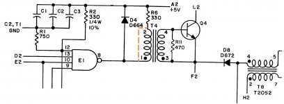
Circuit.jpg

These two measurements are from a chip which still worked. But you can see that the output can't reach 5V.
And that is weird because the chip has a pull up of 330 Ohm trough the transformer.
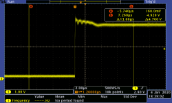
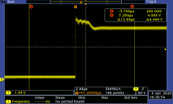
Dying 7440-1 TI 7748 port 1.png Dying 7440-1 TI 7748 port 2.png

The second chip is even worse and the circuit was not working any more. But you can still see the outputs being toggled.
The 2nd output of the chip reaches about 3.5V. Even with the 330 Ohm pull up resistor it can't reach the 5V.
To trigger the pulse trough the transformer the output needs to go low. But this constant current makes the transformer
go into magnetic saturation. And the output pulse will be too small to make the transistor Q4 conducting.
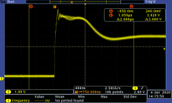
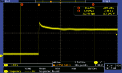
Dying 7440-2 TI 7748 port 1.png Dying 7440-2 TI 7748 port 2.png

I was wondering if the chips could go bad by the induction of the coil. When switching a coil off the coil want to maintain
its current. That is why diode D4 is placed in the circuit. (This is the same reason why a DC relay coil deeds a diode)

To demonstrate this I have shorted the primary coil of T4 (pin 1 and 2). Now you have a nice (almost) flat pulse on the output of the 7440.
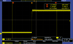
1 G228 shorted transformer.png

Here you see the -switch off- pulse on the 7400 then the transformer is not shorted any more.
You can see the output spiking above 6V. For about 3 micro seconds you can see the transformer ringing
and giving back all the energy which was put in it while the 7440 output was low.
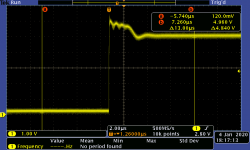
2 G228 Original diode.png

When the diode is replaced by a 1N4149 it spikes even further and you can see a lot of higher harmonics.
I didn't like this behaviour. I'm not sure if this was killing the TI 7440 chips. two other G228 had also
replaced diodes and did not go bad.
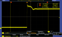
3 G228 1N4149.png

So the final solution. I used BAT85 schottky diodes as replacement on the G228 ONLY for the diodes D1, D2, D3 and D4.
The result is a much more friendly pulse on the output of the 7440 chips.
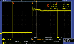
4 G228 BAT85.png

The machine now passes all the toggle in tests. So now it is time to do things with a RIM/BIN loader
and throw some maindecs to it.

Regards, Roland
 
Program 20:
ISZ instructions do not pass the test. I've compared it with the behaviour on my 8/M
and it is a bit different. Does anyone know if there are some more instructions not being
supported on the PDP8/L which were introduced later on the 8/E systems?
Or can anyone confirm the outcome of that program on a PDP8/L for me?

Regards, Roland


ISZ is the same on all machines. The specified memory location is incremented and the next instruction is skipped if the result was zero.

Seems odd that this would have problems if the group 2 and the memory reads and writes are working.
 
ISZ is the same on all machines. The specified memory location is incremented and the next instruction is skipped if the result was zero.
Seems odd that this would have problems if the group 2 and the memory reads and writes are working.

Yes odd indeed, but I think that it was braking down in earlier tests...
That happened also with the AC increment test which you can see in the youtube film.
The machine worked for a while and then stopped. That was the reason for me to replace
all the 512 diodes on the core stack after finding a total of 70 defective diodes on it.

I changed that ISZ test to use another part of memory and then it worked.
That was the reason for me to believe that is was a memory related problem.
Then I checked the address which the loop was using before, one bit gave a failure.
That is fixed and the machine runs all tests from the paper are working now.
But these tests are not the maindec tests off course...

I think it is good to run the maindec tests for a longer time to trigger all the parts
in the machine. These little toggle-in tests just use a very small part of the memory.
(The checker board tests did run but I don't know if that triggers all of the memory)
I expect some more components to break down when the machine has to work hard
with maindecs. But the machine seems to be ready to do these tests now.

I have to connect that current loop port to my PC now. (The RS232 replacement
board designed by Vince is on its way to me, but these are still in China)
I have a RS232 to current loop box. I have to check if that is suitable to use.

Regards, Roland
 
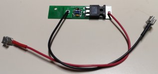
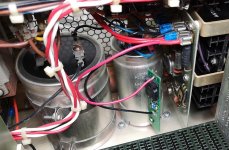
In the meanwhile I've built and tested my crowbar PCB. It trips nicely on 5.8V.
So now I've put it in de PDP8/L. I used the screw of a capacitor clamp to hold the PCB.
Just two wires to connect the GND and +5V will do the job.

PDP8L - 59.jpg PDP8L - 60.jpg

Design files are here: https://github.com/Roland-Huisman/Crowbar_PDP8-L
(I have three spares left if anyone would be interested)

(Like mentioned earlier also by other people, some PDP8/L power supplies have a nasty peak
on the 5V at powering up. This is also mentioned earlier in this topic. If you don't fix that first
this crowbar will trip even before the power is stabilised. So if you want to use the crowbar,
check your power first.)

Regards, Roland
 
In the meanwhile I've built and tested my crowbar PCB. It trips nicely on 5.8V.

Design files are here: https://github.com/Roland-Huisman/Crowbar_PDP8-L
(I have three spares left if anyone would be interested)

(Like mentioned earlier also by other people, some PDP8/L power supplies have a nasty peak
on the 5V at powering up. This is also mentioned earlier in this topic. If you don't fix that first
this crowbar will trip even before the power is stabilised. So if you want to use the crowbar,
check your power first.)

Regards, Roland

I discussed this with a friend not too long ago. Unless the transient goes above 7 volts it should not be a problem for the logic. 7 volts is the absolute max rating. I have run common TTL from batteries at 6 volts for extended periods. They get kind of warm if you try to run them continuously at much over that. So while not recommended for normal operation. a transient of a few milliseconds up to 7 volts should not kill any chips. If the transient goes beyond the 7 volts for even short periods I would be concerned. Look at the bus voltage near where the power supply cables connect with a high speed analog storage scope. Or a really high speed DSO. DSO's can miss the seeing the peak voltage on short transients. The chips themselves will act to damp a transient because they draw more current as the voltage rises. Checking the power supply with no cards installed to see if there is a transient will almost guarantee that there is one.

Where does this transient come from? Is this some characteristic of a Ferro Resonant transformer I am not familiar with?
 
Where does this transient come from? Is this some characteristic of a Ferro Resonant transformer I am not familiar with?

Hi Doug, this comes from the differential amplifier which is not working
up to a certain level of mains power voltage. When you slowly rise the mains
voltage it just stays at 6.3V. When you raise it further then suddenly the differential
amplifier starts to work and the output voltage drops to 5.1V.

I agree that the 6.3V is not dangerous for a short moment.

But I know of at least one fried PDP8/L from a forum member. This machine has almost all
TTL chips killed by a power supply failure. Since the TTL chips are protected by the same
components which are the voltage reference in the system, I wanted make it safer...

That is why I added a relative cheap crowbar circuit and modified the power supply.

Regards, Roland
 
The PDP8/L passed all maindecs!

So now it is time to have some fun with the machine.
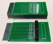
I made a few cards to play with the bus of the machine.
PDP8L - 61.jpg

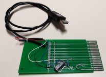
Because I'm still waiting for the replacement boards from china for the serial clock
and RS232 connection, I have turned one of these boards into a serial to USB converter.
In the USB plug itself is a USB-RS232 on TTL level chip. I only needed an inverter to make it work.
PDP8L - 62.jpg


And I found come pictures on the web from the PDP8/L desktop version.
Does anyone have some clear pictures and sizes of that case? I really like
the looks of that black case around the PDP8/L. Maybe it is possible to make a replica?
If anyone has such a case for sale I'm also interested off course!

PDP8L - 99.jpg

Regards, Roland
 
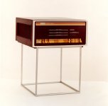
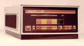
Here are a couple 8/L glamour shots from DEC Sales and Marketing:

View attachment 58649

View attachment 58650

Here's a similar case for the 8/E:

View attachment 58651

That image kind of reminded me of my NOAA days when I was the tech aboard a ship whose task it was to plot and mark the bays and inlets in Lake Huron. Our job was to coordinate sonar depth soundings with strategically placed Del Norte TACANs along the shore line. All of this data was feed into the PDP-8 and then passed back to HQ at the Atlantic Marine Center for processing into future charts. When visitors came aboard they were treated to a computer generated drawing of a sailboat done with the PDP-8, and then rendered on the plotting table. BTW, that was over 40 years ago
 
On the 8/E? Yes. The power supply is located there, along with fans. A filter is a good idea.

What kind of filter element was used on these?

While my rack mount Straight 8 has filters on the intake fans in the bottom of the racks none of my other 8's do. I guess I never saw a non rack mount 8/e. In particular one of my 8/a's could have really used one. It was a CNC controller and the fan side of all the boards were coated with a metallic residue. This was also on several spare boards I purchased. I assume it was metal particulates suspended in oil. A wonder that it didn't short stuff out. It is interesting that the fan blades didn't show signs of this. Some of the fans had been replaced and the rest were in sorry shape so I swapped all of them out for modern low noise ones. The loudest thing in that machine is now the transformer hum (and the head load mechanism on the RX01's of course.) Makes it a pleasure to be next to. The power supply area could use a little more airflow but the card cage airflow is adequate. At least for the card load I have in that box.

I don't have any details of the filter. Maybe there is some documentation somewhere on bitsavers?
The rackmount version have (if I remember mine right) just this usual DEC stuff that disintegrates with time, which was glued on to the box.
I would suspect the version in the picture used the same horrible stuff inside. :)
 
Here are a couple 8/L glamour shots from DEC Sales and Marketing:

Hi Jack,

Thanks! What a wonderful pictures. I hope someone has clear pictures
about how it is really attached to the PDP itself. Or maybe some sizes and
pictures of the cabinet itself without the PDP...

Regards, Roland
 
Back
Top