• Please review our updated Terms and Rules here

Kaypro 4/84

Formulator

Experienced Member
Joined
Apr 17, 2015
Messages
141
Location
Dallas, TX
I have a Kaypro 4/84 Plus 88. It is exhibiting a new issue in which some of the characters appear broken, particularly on the right side of each character, and some have portions that appear more dim as well. I have attached a sample image of the display. This is again a new issue and has not occurred before. It has been about a year since it the unit was last powered on. Please let me know if anyone else has had this issue before, and if it was solved. Thanks.
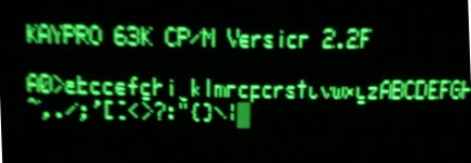
IMG_0723s.jpg
 
My first guess would be one of the data lines between the character-generator ROM (at U9) and the aux-CRT-circuitry (81-189 at U10) has lost continuity. You might have to (carefully!) re-seat those ICs (hopefully that's all it is). Otherwise, an output driver on the character-generator ROM has blown, Or (worst of all) an input on the 81-189 (cannot be replaced with new parts, must be scavenged).

Based on the pattern in the photo, it would appear to be D1 that is not making connection. U9 pin 12 or U10 pin 18. It's also possible that a solder connection to the socket has failed, or the trace between.
 
Here is a bit more information I OCR'd.
Code:
CHARACTER ROM D3

A 2716 (2K x 8) EPROM is used to store the dot information for
every character displayed.  Each character is set in an array of dots,
8 rows and 8 columns.  Only 5 of the the columns are used for each
character.                                                                                                                        

Eight bytes are used for each character, one for each row. Seven of
the rows are used for the character body and the bottom row is used
for descenders. The 0 bits are displayed as lighted dots.

The ASCII data in the video RAM points to the character and the
scan clock adds the low order three bits to se!ect which of the eight
rows (O-7) of that character will be displayed.

Since only 5 columns are used, D5-D7 have no connections from
the ROM.

CHARACTER TO VIDEO
CONVERSION-D3-

As each row of dots is addressed, the hex D flip-flop U42, samples
the byte as it is clocked in by DCTC.  U41 then multiplexes the
parallel dot pattem out to the video driver one dot at a time.  While it
is doing this, U42 is getting the dot pattern for the next character.
 
  U#             Device                        Location               Description

  Y1             CRYSTAL                       A5                     13.9776 MHz crystal
  U1             74LS161                       A5                     Parallel loading binary counter
  U2             74HC04                        A5                     Hex inverters
  U3             74LS290                       D5                     Decade counter
  U4             74LS10                        A4,C5                  Triple three input positive NAND
  U6             74LS393                       B5                     Dual 4 bit binary counters
  U9             74LS08                        C5,D2,D4               Quad 2 input positive AND
  U10            74LS32                        D4                     Quad 2 input positive OR
  U11            74LS393                       C5,D5                  Dual 4 bit binary counters
  U12            74LS74                        A5                     Dual D-type flip-flops
  U14            74LS74                        C5,D5                  Dual D-type flip-flops
  U15            74LS00                        C4,D2                  Quad 2 input positive NAND
  U16            74LS157                       C5                     2 to 1 line multiplexer
  U17            74LS157                       B5                     2 to l line multiplexer
  U18            74LS157                       C5                     2 to 1 line multiplexer
  U19            74LS157                       B5                     2 to l line multiplexer
  U28            2114                          C5                     1K x 4 static RAM
  U29            2114                          C5                     1K x 4 static RAM
  U30            2114                          C5                     1K x 4 static RAM
  U31            2114                          C5                     1K x 4 static RAM
  U32            74LS74                        D4                     Dua1 D-type flip-flops
  U41            74LS151                       D3                     1 of B data multiplexer
  U42            74LS174                       D3                     Hex D-type flip-flops
  U43            2716                          D4                     2K x 8 EPROM containg character set
  U44            74LS243                       B4                     Quad bus transceivers
  U45            14LS243                       B4                     Quad bus transceivers
  U56            74LS02                        B4                     Quad 2 input positive NOR
  U58            74LS138                       B4                     3 to 8 line decoder

And finally a small BASIC program that may help.
Code:
10 DATA 1,2,4,8,16,32,64,128     ;65407,65471,65503,65519,65527,65531,65533,65534
;       1,2,4,8,16,32,64,128,!128,!64,!32,!16,!8,!4,!2,!1
50 FOR X = 12288 TO 13311        ;0x3000 to 0x33FF
60 FOR Y = 0 TO 7                ;0 to 15
70 READ Z: POKE X,Z
80 IF (PEEK (X) AND Z)=Z THEN 90 ELSE 150
90 POKE X,0
100 IF (PEEK (X) AND Z)=0 THEN 110 ELSE 150
110 NEXT Y
120 RESTORE:NEXT X
130 PRINT "VIDEO MEMORY GOOD"
140 END
150 PRINT "BIT''; Y;"OF MEMORY LOCATION"; X;"CHECKS BAD"
160 GOTO 110


Larry
 
Addendum to Larry's information: The character generator ROM described above is for the Kaypro II/IV. Later models (2X, 4/84,...) use a larger ROM (2732), 16 row by 8 column character cell, and there is character data in all of the 8 columns.
 
Addendum to Larry's information: The character generator ROM described above is for the Kaypro II/IV. Later models (2X, 4/84,...) use a larger ROM (2732), 16 row by 8 column character cell, and there is character data in all of the 8 columns.

Oh, and another difference. The Kaypro II/IV have direct access to the video RAM (when the ROM is enabled via the system port), but all the later models (incl. your 4/84) hide the video RAM behind the 81-189 and CRTC chips. You won't be able to easily test that RAM in a simple program. Also, the symptoms you show are not likely caused by bad video RAM anyway. It all points to the character generator and associated circuitry.
 
Update, I have carefully re-seated the ROMs and confirmed that there is indeed continuity between U9 & U10. No change in behavior. I have a 4/83 model which I believe contains the same character ROM. I will try swapping it out and report back. Thanks to all for the advice given above thus far.
 
Unfortunately, the 4/83 does not contain the same character ROM. Next step is to source/produce a new 81-235 ROM and go from there.
 
Revisiting this issue. My primary source for producing a ROM is unable to create an 81-235. If there is anyone willing to create thIs ROM for me please let me know. Thanks.
 
Can you get a good photo of U9 81-235 Character ROM (2732) so I have the Manufacture's part number and speed of that ROM(EPROM).
I can burn the TMS 25xx Series and 2732's with my BP Microsystems EP1 programmer. I do have the Character ROM file on my computer.

In looking at the schematic, the Character Generator is using Address Lines {0..12}, which is 2^13 = 8192 Address Locations.
A 2764 EPROM has the same 28 Pins as the 81-235 Character Generator. So, you should be able to program a 2764 EPROM,
plug it in your IC Socket and be up and running.


Larry

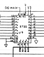
Click image for larger version  Name:	K4-84-U9.png Views:	0 Size:	124.0 KB ID:	1227940
 
Last edited:
Since all 16 Rows {0..15} are correct for each character, the problem has to be Out1 (Pin 12) of U9, because one bit to the right
Out0 is being displayed.


U9-----------U10

Pin----------Pin
11 Out0---17
12 Out1---18
13 Out2---19
15 Out3---21
16 Out4---22
17 Out5---23
18 Out6---24
19 Out7---25

Can you remove U9 and U10 and OHM the above IC socket Pins of both sockets. Pin 11 of U9 to Pin 17 of U10, then Pin 12 of U9
to Pin 18 of U10. This should be the problem PCB trace.

Doug, Do you know what Pin 2 A12 CH of U9 does to Hide the ROM. It looks to be just selecting the High 4096 bytes of the ROM,
which I assume is all zero's versus being 0xFF.

Larry
 
As I recall, the larger ROMs could have different character sets (alternate language, I think) and so you could switch by changing a bit in the control port (i.e. under software control). Obviously, you couldn't use both character sets intermixed on the screen - the CRT controller just refreshes the entire screen with whichever set is selected. I don't think I've ever seen an image for the larger ROMs.
 
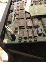
This is a pic I had on hand when I first opened the unit a few years back. I can get a better pic if needed. I will report back with findings about U9 & U10. Thanks.

IMG_0036.JPG
 
As I recall, the larger ROMs could have different character sets (alternate language, I think) and so you could switch by changing a bit in the control port (i.e. under software control). Obviously, you couldn't use both character sets intermixed on the screen - the CRT controller just refreshes the entire screen with whichever set is selected. I don't think I've ever seen an image for the larger ROMs.

Yep, I've a Kaypro 2 with an alternate Greek character set, it can be enabled/disabled with escape sequences
 
AH! That Photo shows they used a 24 Pin ROM Character Generator in a 28 Pin IC Socket.

I've decoded the Character set and have it attached.


Larry
 

Attachments

  • kay4-84.txt
    88.2 KB · Views: 6
Back
Top