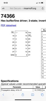
I took a stab at reading the input on this chip. I referenced the attached data sheet and found pin 13. Am I reading that right? Regardless I got no signal on any of the pins on that chip. Only some highs and lows. I did see some wave forms in the 28 pin Z4 chip but not on the corresponding pin19. Because of that I feel like the scope is connected properly and functioning as it should. Perhaps that 366 chip is bad as suggested above?
- VCF South West - June 14 - 16, Davidson-Gundy Alumni Center at University of Texas at Dallas
- VCF West - Aug 2 - 3, Computer History Museum, Mountain View, CA
- VCF Midwest - Sept 7 - 8 2024, Schaumburg, IL
- VCF SoCal - Mid February 2025, Location TBD, Southern CA
- VCF East - April 2025, Infoage Museum, Wall NJ
-
Please review our updated Terms and Rules here
You are using an out of date browser. It may not display this or other websites correctly.
You should upgrade or use an alternative browser.
You should upgrade or use an alternative browser.
Keytronics keyboard rebuild question model 2
- Thread starter TXNathan
- Start date
shirsch
Veteran Member
If you don't see activity on pin 19 of Z4 then the MCU is bad. But, it seems like a very unlikely failure. Have you verified that the keyboard electronic are getting +5V and ground connectivity?
Hi thanks,If you don't see activity on pin 19 of Z4 then the MCU is bad. But, it seems like a very unlikely failure. Have you verified that the keyboard electronic are getting +5V and ground connectivity?
Yea I see 4.9 volts across from he power pin and the ground pin on the connector to the keyboard circuit board
Taking another look at this tonight. If I read it correctly it sounds like the clock signal for the keyboard is generated on the keyboard pcb? Perhaps in that rom chip? For something to do I thought I could just feed the 5V in and ground from my bench supply and look for the clock again. That takes the computer out of the equation. I tried to buy another keyboard on eBay today but lost it at 103$.
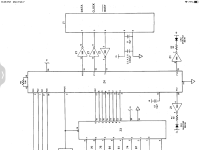
I isolated the keyboard PCB on the bench today so I could poke around some more. I supplied it with 5V from my bench power supply and while I was able to find a lot of clock noise with my logic probe I couldn’t find a nice square clock signal with the scope. I had ordered a few 74LS366 from Jameco last week to go ahead and try that as mentioned above. I socketed the spot and will try that Tuesday when they get in. If there is still an offer to check a known good one for some signals and post them I can try to replicate the set up and see what I get. On the schematics posted I am not sure I fully understand the pin numbering on the drawings. For example there will be a number inside the chip block drawing but a different number right next to it on the drawing. It seems the number in the block is the actual pin on the chip but what is the other number referencing?
for example in the schematic above one pin is labeled P11 and 19
for example in the schematic above one pin is labeled P11 and 19
The new hex buffer should be here tonight. I have it socketed So hopefully that’s it. If not the MCU appears to be Z4 which is an Intel P8021. Is this a ROM chip? It’s obsolete but I found a pair on eBay. If it’s a preprogrammed ROM I am guessing these would not work
Grasping at straws at this point
Thanks for any help or guidance. Nathan
Grasping at straws at this point
Thanks for any help or guidance. Nathan
Alright. Some progress but not much. Really could use some input…..
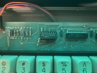
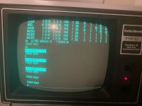
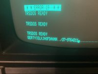
new 74LS366 hex buffer came in today From Jameco. Installed and powered up and some keys work. I took a screen shot of the new chip, the trsdos screen I was finally able to get to and the command line with all the keys that worked. None worked before except some numbers.
am I right in thinking if some keys work then the logic part of this problem is operational and now it’s just figuring out why some parts of the board are non responsive? Surely there is not a section of the rom chip and buffer that only address certain keys. I played with this for a while just to be sure some would not work intermittently. its pretty consistent but I feel like all are slow to respond
not getting many responses anymore,