• Please review our updated Terms and Rules here

Lear Siegler ADM-31 Repair

lgallair

Member
Joined
Aug 13, 2015
Messages
22
Location
Canada
Hi there,

I'm trying to fix a Lear Siegler ADM-31 dumb terminal I purchased on Kijiji and I'm hoping to get some guidance on this forum as to how to proceed next. When I initially powered it on, it beeped once before I heard a "pop" and then a little puff of smoke coming out from the back. Upon inspection, I found a burnt tantalum capacitor on the power supply. Replaced it as well as all the electrolytic caps on the power supply and monitor chassis. After that was done, the power supply only made clicking noises.

I found a schematic of the power supply and started to replace components I thought might be causing the problem. Well, after replacing almost every component I finally got the power supply to produce the proper voltages, albeit with a steady high-pitch hum. The problem component turned out to be the opto-coupler.

Confident that I got the power supply working, I connected the mother board to the power supply and turned it on. The monitor displays a vertical green line, makes one continous beep, and the red light on the keyboard is on steady. After about 10 seconds, the vertical line fades away. If I disconnect the monitor from the motherboard, it still makes a continous beep and the red light still stays on steadily. Playing with the pots on the monitor chassis does nothing except for the width coil. If I turn it a certain way with a plastic allen wrench, the monitor will cycle between a vertical line and a horizontal line and beep once every 1/2 second.

It's at this point where I'm stuck as to what to do. Is it a problem with the monitor chassis? Or the motherboard? Or both? How do I diagnose the problem? It's either a short or a bad transistor on the chassis and a bad IC on the mb. I double-checked all the cap's polarity ... all good. The large cap (filter cap?) is a lot smaller than the original so that has me concerned. Did I buy the right one? Same capacitance and voltage rating, just 80% smaller in diameter. I managed to find the manual and schematic for the monitor used in the ADM-31 from the ADM-36 maintenance manual. Apparently the ADM-36 used the same monitor.

My electronic knowledge is average. I know what most components do and can solder. I have an IC tester, IC probe, Multi-meter and an Oscilliscope that I purchased just for this project.
I'm determined to get it working.
 
It's also possible to fry the bridge rectifier, we had one at Festivus go that way.
 
Sounds like it might be the horizontal deflection transistor, they are generally in a TO3 package so not hard to spot.

There's only three transistors on the chassis (2N2219, KCS1008, and BU407) and I'm not sure which one would be in a TO3. From the schematic, there's a "H DRIVE" label which leads to the KCS1008 and BU407. Would it be one of these? I'm not very familiar with how CRT's work. I know how to properly discharge one but that's about it.
 
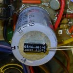
Here's a picture of the original Filter cap and the replacement I bought from Digi-Key. The original is a 16uf 63V B.P. cap. I could not find an exact match so went with the closest which was a 10uf 63V B.P. but as you can see from the pic it's a LOT smaller. This has got me thinking that perhaps I did not buy the correct one. I read somewhere that a 10uf was a suitable replacement for this cap. Does anyone have any advice on this one?

Filter Cap.jpg
 
I replaced the Horizontal Output Transistor as David_M suggested that may be the problem, but that did not fix it. Still exhibiting the same monitor flashes. I made a short video of what is happening when I power it on. I'm sort of shotgunning it by replacing random parts. Any help would be appreciated. Thanks.

 
Why are you assuming it's the monitor circuit that's broken? It might be the video and/or HV synchronism are not correctly generated by the logic board.
Do you have an oscilloscope?
Regards

Frank
 
I do have an oscilliscope but it's an old Telequipment S54A with one channel. I also have an isolation transformer.

When I disconnect the cable to the monitor and only power the main pcb, I get a continuous beep from the little speaker, so I know that there's a problem there somewhere.
I'm not sure why I would think the problem is with the monitor circuit. Without a schematic, I don't know where to begin probing.
Could I somehow test the monitor without the main pcb connected? Using a pattern generator, maybe?

I'm really trying hard to learn all these electronic circuits but there's times where I want to throw it all in the garbage. Thankfully I'm no there yet.

Your oscilloscope might be enough for the task: you need to check the video, H sync and V sync signals going from the main PCB to the monitor. I do suspect they aren't correct. Those old monochrome monitor circuit are usually simple and reliable enough. I've usually found many of them still working perfectly after all these years.
Frank
 
Here's a picture of the original Filter cap and the replacement I bought from Digi-Key. The original is a 16uf 63V B.P. cap. I could not find an exact match so went with the closest which was a 10uf 63V B.P. but as you can see from the pic it's a LOT smaller. This has got me thinking that perhaps I did not buy the correct one. I read somewhere that a 10uf was a suitable replacement for this cap. Does anyone have any advice on this one?

Sorry for the late posting, but I haven't been following this thread.

Yes, there are differences among types of bipolar/nonpolar electrolytics. Because yours is in the deflection circuit, you need to use a high-frequency capacitor. There are special-purpose ones made for horizontal deflection applications:

https://www.tedss.com/DataSheets/2020/2020070154.pdf

In other words, any old bipolar cap won't do!


Yes indeed, I've missed that post too! And I can't see why the original capacitor should be faulty too... I would leave any component alone if that's not really faulty and tested as definitely bad with some sort of test equipment or, well, exploded maybe :)
Frank
 
I'm afraid I threw out the old capacitors when I re-capped the monitor chassis. I read on various sites that on these old boards, it is best to replace all the electrolyic caps, so that's what I did. Never thought of keeping the old ones just in case.

The capacitor I originally bought to replace the filter cap was just a general purpose 10uf 63V BP cap. It didn't look right in that it was sigmificantly smaller than the original.

So I searched around for another replacement and found an Elna NP 100V 16uF Bipolar Electrolytic Capacitor. That's the one I have currently soldered in place and giving me what you see in the video.

Now, going by Chuck's post above, I went ahead and bought a Xicon BPHR50V10 50V 10uF 85°C Aluminum Electrolytic Capacitor off eBay. When this arrives, I'll remove the Elna and solder in this one.

Like I said, I'm not very knowledgeable when it comes to electronics but I am trying to learn. I would have never thought that I needed a High Frequency BP cap. All the manual says is it needs to be Bi-Polar. If anything, I learnt that.

Thanks guys. I'll post back when I have the part and fired up.
 
The high frequency bipolar cap arrived the other day and I installed it. Still same symptoms as before. There are two crystal oscillators on the main pcb. One tested fine but the other did not. It's labelled 19.584Mhz but only tested as 6 Mhz. I ordered a replacement from digi-key. It arrived shortly after the bipolar cap did. Installed it but that did not fix the problem either.

I was speaking to a friend of a friend who once owned an electronics repair store fixing TV's and such. He's retired now but after explaining the symptoms he thought maybe the issue is with the switching power supply. Since I briefly get a vertical line then it collapses, a horizontal line then it collapses. He thinks the smps is shutting down and recycling. My original problem was with the power supply but I had thought it was fixed once I was receiving the proper voltages. He told me that even though the voltages are fine, they may drop once a load is put on them.

I cannot find a replacement smps that has the same voltages I need (+5, +18, +12, -12) so I'm left with fixing the original. Can anyone suggest what might be the problem with the smps that would cause it to shut down and restart? Feedback circuit? I don't know much about these smps so in the meantime, I will try to learn what I can from youtube and the internet. If you can help I would really appreciate it.
 
How does one test a monochrome CRT to tell if it's working? The pinout on the header has Vsync, Hsync and Video. Do I need a test pattern generator? Is there something that I can build myself to test the monitor? Can I hook up another device which outputs video to it?
 
How does one test a monochrome CRT to tell if it's working? The pinout on the header has Vsync, Hsync and Video. Do I need a test pattern generator? Is there something that I can build myself to test the monitor? Can I hook up another device which outputs video to it?

Sorry if I insist, but you seem to walk the wrong path to a successful repair. The monitor circuit was probably fine from the beginning, you should look at the input signals, Vs/Hs/Video and see what they look like on an oscilloscope. You'll probably find that one or both syncs are missing or maybe the Video signal is "flat". You "could" reproduce the three signals but probably not with any standard video generator.
As for the power supply, does one or more of the power rails show a wrong value? It takes only a multimeter to check this, and it's always the first step when repairing any piece of hardware.
Frank
 
I took your advice Frank and tested the power supply with my DMM. It's definitely the problem.
Funny thing is though it tested fine with no load. Sometimes, not all, I could even connect the main pcb and get all the proper voltages.

These are the voltages from the manual that I need to supply on each rail.

+5v
+12v
-12v
+15v

Respectively, these are the voltages I get with just the power supply (nothing hooked up to it).

+5.04v
+11.97v
-10.18v (a little low)
+15.34v

Respectively, these are the voltages I get when I connect just the main pcb (no crt).

+6.8mv
+7.03v
-19.87v and steadily dropping
+13.79v and steadily dropping

When I connect the crt, I get the intermittent lines on the monitor (horizontal then vertical then horizontal then vertical, etc).
The 15v going to the monitor also measures irratic with my DMM.
Besides the continious beep from the speaker, I also hear a clicking noise coming from the power supply at the same frequency as the lines on the crt.

I'm googling and youtubing clicking smps for a possible cause.

I think your power supply is fine. You should look for a short circuit (probably a bypass capacitor) on the main PCB.
What happens: the SMPS tries to start, but current limit kicks on, due to the short circuit on the 5V rail, then it shuts off (clicking sound) and
after a while it starts again, overcurrent kicks on again and the cycle repeats forever (or when you remove the power).
Frank IZ8DWF
 
Thanks Frank.

So, assuming that the PS is working, I directed my attention to the main PCB in an attempt to locate a short. With my DMM in continuity mode, I probed every component on the PCB with the exception of the IC's. The only component that "beeped" when I touched both ends was a ceramic capacitor out in the middle of nowhere. Thinking this was the fault, I eagerly de-soldered it and re-tested hoping it would resolve my problem, but no such luck, the cap tested fine out of circuit. Then I touched the ends of the probes to the two solder pads where the cap used to be be and it "beeped". Okay, progress, or at least a clue. I followed each trace to determine what they went. One led to the GND pins of several IC's on the top layer of this 2-sided PCB. The other also led to GND on the bottom side. What gives? Both ends can't be GND can they? Why would they place a capacitor between the top and bottom GND traces? I'm so confused. Going to bed to think about it and wrap my head around it.

You're not going to find the short easily with the "beeper". I usually have more luck with 4 or 5 digits voltmeters with probe resistance zeroed. I can usually find after some hours the point with least resistance value and that's usually a capacitor.
All the ceramic (or almost all) that you can find on a digital PCB are sitting across +5V and GND, they're 'supply bypass'.
With the shorted +5V, each capacitor should "beep" your multimeter. You should also measure a short between GND and VCC pins of any 74xxx chip, they are usually the bottom-left one (GND) and the topmost-right one (VCC) when looking at the chip with the notch UP.
Another method I use when looking for a short is using an HP pulser and HP current tracer, but these are hard to find tools nowadays.
Another method (but be careful) is to power the 5V rail with a 5V current limited power supply, set the limit to say 0.5A and see what smokes or becomes very hot. You must understand what you're doing anyway, so don't blame me if something explodes.
Frank
 
Back
Top