• Please review our updated Terms and Rules here

Lisa CRT replacement

You need to verify that the new yoke is compatible. Find out which pair of wires is horizontal and which pair of wires is vertical. Using a meter, get a resistance reading from each pair, then compare that reading to the old yoke (or vice-versa depending on which one you start with). If each reading is within a few ohms of the other, you're good, swap it in. If one or both readings are drastically off (50 ohms instead of 3 ohms), then you'll need to swap the yoke. On a monochrome, a lot less to work about with yoke swapping, as long as its installed snug against the bumpers minimal adjustment should be required.

I did a write-up for arcade monitors, some of which may apply: http://www.junknet.net/tube-swap-diy-part1

Thanks for the replies and thank you, orion3311, for the post. I actually read your page a couple of times and was going to look for it again. I don't recall the part about checking with an ohm meter but, sure enough, it's there and will help. I am probably more likely than not going to swap the yokes as long as they come off easy. Looking at it from the neck to the tube, and considering the yoke is like a dial, I'll make sure it's dialed in at 12 o'clock exactly like it was on the old tube. Do I have to worry about in and out or do I just make it snug fit?

I also have the DAG wire that's on the new tube's yoke. Do I need to worry about the fact that the old yoke doesn't have one?

Thank you all!
 
If you get this (swapping the yokes) to work (which I sincerely hope you do), think you could do a video using the leftover parts explaining/showing what you did? It's totally up to you. Either way I'm pulling for ya!
 
Yeah, there is really very little to monochrome yokes, worst case the image is a bit crooked if you aren't lined up quite right once you swap the yoke in.

Now that you mention that, my Lisa's CRT display is slightly crooked a few mm from the previous owners burn in when I got it. Is that just a easy slight rotation adjustment {yoke clamp) after I obviously discharge it ?

Cheers,

-Nick
 
If you get this (swapping the yokes) to work (which I sincerely hope you do), think you could do a video using the leftover parts explaining/showing what you did? It's totally up to you. Either way I'm pulling for ya!

I had a friend come over who has worked with CRTs before ans we worked on it together yesterday. I felt kinda odd asking him if I could video tape the event so I apologize for not recording it :)

It was a fairly simple procedure once you know your CRT is discharged (mine was already discharged) and you have a second set of hands.

Removing the CRT
1. Discharge the CRT
2. Remove the anode wire
3. Remove the two horizontal/vertical connectors that come out of the bottom of the yoke. On mine, you don't have to know what way the connector goes because it only goes one way but you DO need to remember which connector goes where.
4. take off the CRT/yoke protector metal bracket. Three screws on the inside enclosure right next to the tube neck (two on the sides, one above) and one on the other side where the boards go.
5. Remove the four front screws while someone supports the CRT tube
6. Wiggle off the round CRT neck connector on the end (being very careful).
7. Take notice of how the yoke is positioned. You can look where the yoke vertical/horizontal wires are connected but inside, I noticed the two coils of wire were separated between top half and bottom half. My yoke had two plastic "nubs" that stuck out at the sides. If these are aligned horizontally, then it should be semi-okay in terms of adjustments (I hope)
8. Remove the yoke by loosening the one clamp on the neck and carefully slip off the yoke.
8. Once the CRT is free of the chassis, one screw on the yolk needs to be loosened and then you can take the yoke off.

Mine was broken within the yoke so I had to clean off some glass inside the yoke. I'm not sure if there was any adhesive in there but I did have to scrape glass off of the inside diameter.

I decided to replace the yoke on the replacement CRT with the original yoke for two reasons. The first was due to advise here that makes sense and the second is because the vertical/horizontal wires were in one connector and the original yoke had two two-wire connectors. I didn't want to cut and splice wires or modify the connector so this was easier but I'm still a little worried about the DAG wire, that I did NOT put on.

Replacing the CRT
1. From the replacement CRT, remove the old yoke if there is one
2. Place the new yoke on the replacement CRT and adjust
3. Since I had two plastic "nubs" on my original yoke, I used those to line up the yoke and then screwed the clamp tight.
4. Wiggle on the round CRT neck connector on the end (being very careful).
5. Replace the four front screws while someone supports the CRT tube
6. Put on the CRT/yoke protector metal bracket.
7. Replace the two horizontal/vertical connectors that come out of the bottom of the yoke.
8. Replace the anode wire

You're done!

Now, the only issue that I cad was that I couldn't try it. My I/O board needs work (if I can bring it back from the dead) and my power supply possibly needs work too because my Lisa is completely dead. Sadly, I can't claim success because I don't know if this works. I do know I'm a step closer to getting my Lisa fixed, I hope.

Sorry I couldn't provide a video or proof that it works but I hope this was useful.
Nice job man! Also did you notice if their was any screen burn ect of your replacement CRT that you could tell if it was a used one? I may do this same conversion if they can guarantee those are NOS units. And just sell the yoke it came with. Also I did see one parts power supply on Epay for a low starting bid you might be able to swap parts from. If yours is the 1.2 amp version. Good luck :D

Cheers,
 
Nice job man! Also did you notice if their was any screen burn ect of your replacement CRT that you could tell if it was a used one? I may do this same conversion if they can guarantee those are NOS units. And just sell the yoke it came with. Also I did see one parts power supply on Epay for a low starting bid you might be able to swap parts from. If yours is the 1.2 amp version. Good luck :D

Thanks Nick. I think there may be some traces of burn-in but it's difficult to tell. I also have the privacy cloth over the screen on my front panel so if it's even distinguishable, you can't tell. The CRT I ordered was not advertised as a NOS so I didn't expect it to be. If you decide to go ahead, don't worry about shipping. They really pack it well and wallpaper it with warning stickers.

I'm now going to focus on my I/O board this weekend and see where I get first. If that still fails to get some life out of the Lisa, I'll work on the power supply next. I'm not sure a second bad power supply will be useful. I'll recap this one and I believe I read that the "triac" goes on them and can make them appear "dead"? I do have a 1.2 amp power supply but we'll see where I get.

Thanks to everyone for the encouragement. I'm not sure if it will work in the end but I'm now able to troubleshoot the rest of the Lisa until it finally turns on.
 
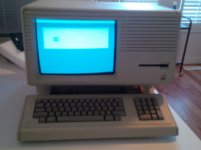
Just an update on where I am. The DEC CRT WORKS beautifully and there is absolutely no burn-in!

lisa_screen_small.jpg

You will notice that it's slightly off. I need to rotate the yoke just slightly clock-wise by a couple of degrees but I eyeballed it pretty good :) When I first turned it on, it was about 25% smaller but centered so I adjusted it with the trim pots and it's pretty good now. Just to recap, I replaced the yoke from the broken CRT and I am off to the races.

Note: I have the Mac XL screen mod on this unit so I've got square pixels, if that makes a difference to anyone who may want to attempt this.

Now I have the dreaded I/O error 52 to deal with and will need to hunt down a COP421, I think. My COP421 socket was pretty corroded so I replaced it and checked connections from each COP pin to it's mate and it looks okay :(
 
I'm curious about the phosphor persistence on the new CRT... when you move an image (like the mouse pointer, or scrolling text), does it smear?
 
I'm curious about the phosphor persistence on the new CRT... when you move an image (like the mouse pointer, or scrolling text), does it smear?

Unfortunately, I'm stuck at a static "Error 52" with a long-short-long beep and no where to go. I have no mouse cursor at that point and cannot turn off the Lisa. When I get further, I will certainly post.
 
Just to close this off, after getting the parts to finally put the Lisa 2/5 together, the replacement DEC CRT works great! Not a trace of burn in and no phantom mouse tails because it's too slow. As noted before, this even has the square pixel video mod on it so it's got the Mac resolution.

In case anyone is still wondering, it's fine.
 
Small bump to this thread: If you want to see a video of swapping a Lisa CRT, I filmed one a while back.

https://www.youtube.com/watch?v=Oauo8NQYomo&t=130s

The original CRT is a P7 phosphor - 2 layers: white closes to the face, and green / yellow behind. As the tube gets more burnt in, the brightness gets turned up more which activates the green phosphor more. This leads to a smeary display.

Thanks,

-J
 
Back
Top